Delivery device

Pending Publication Date: 2021-05-27
SHANGHAI MICROPORT CARDIOFLOW MEDTECH CO LTD
View PDF0 Cites 0 Cited by
  • Summary
  • Abstract
  • Description
  • Claims
  • Application Information

AI Technical Summary

Benefits of technology

[0021]In the provided delivery device, the distal end of the sheath tube is fixed to the guide tip, and the implant is loaded into the delivery device by the proximal end of the sheath tube. During deployment of the implant, the sheath tube is caused to move toward distal end, that is, the sheath tube continues moving to the target site of the implant, rather than moves backward to the handle. This can effectively circumvent the problems that may arise from retraction of the sheath tube through a three-dimensionally curved path, such as unstable or even faulty deployment

Problems solved by technology

The mitral valve is structurally more complicated than the aortic valve due to high shape irregularity of the annulus, multiple chordae tendineae in the ventricles of the heart that may seriously interfere with the implantation and positioning of the prosthetic valve, as well as very high intracavitary pressures generated by ventricular contraction.
Therefore, an improper design of a positioning device may become a direct cause of a series of fatal complications.
As a result, it will be difficult to retract the stiff sheath tube (which is a straight tube) through the curved path (which conforms to a radius of the anatomical ge

Method used


Image

  • Delivery device
  • Delivery device

Examples


Example

Embodiment 1

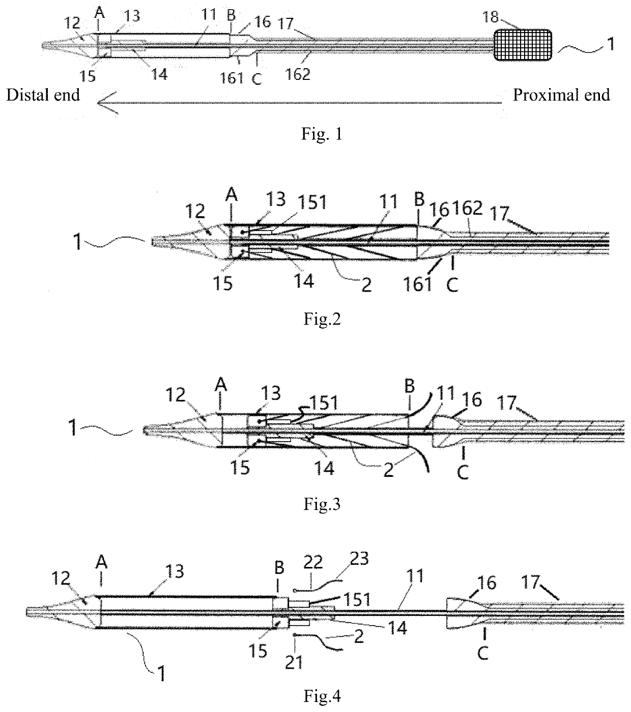
[0034]As shown in FIG. 1, a delivery device 1 according to this embodiment is composed of a catheter assembly and a handle 18. Specifically, the catheter assembly includes an inner tubular core 11, a guide tip 12, a sheath tube 13, an inner tube 14, an anchor 15, a transition member 16 and a bending controllable tube 17.

[0035]A proximal end of the inner tubular core 11 is coupled to an inner tubular core actuation member arranged in the handle 18 so that the handle 18 is able to cause axial movement of the inner tubular core 11, and the inner tubular core 11 is fixed at a distal end thereof to the guide tip 12. The sheath tube 13 has a distal end in a smooth and fixed connection with a proximal end of the guide tip 12 at position A. The sheath tube 13 is sleeved over the inner tubular core 11. In this way, the inner tubular core 11 can be driven to cause axial movement of each of the guide tip 12 and sheath tube 13.

[0036]Optionally, the guide tip 12 is streamlined in des...

Example

Embodiment 2

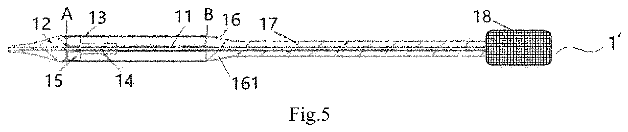
[0061]The transition member 16 of Embodiment 1 is complicated in structure because it includes the transition section 161 and catheter section 162, in communication with each other. Such structural complexity will also complicate the implantation of the implant 2. In view of this, as shown in FIG. 5, an implant delivery device 1′ according to Embodiment 2 includes a modified transition member 16.

[0062]As shown in FIG. 5, according to Embodiment 2, the transition member 16 includes only a transition section 161 without a catheter section 162. In this case, the transition section 161 is directly coupled, at a proximal end thereof, to the distal end of the bending controllable tube 17 by a smooth and fixed connection, and the axial movement of the transition section 161 is controlled by axial movement of the bending controllable tube 17. Other components of the implant delivery device 1′ according to Embodiment 2 are the same as those of Embodiment 1, and a further descript...


PUM


Abstract

A delivery device (1, 1′) for loading, delivering and deploying an implant (2) includes a handle (18), an inner tubular core (11), a sheath tube (13) and a guide tip (12). The inner tubular core (11) is coupled, at a proximal end thereof, to an inner tubular core actuation member arranged in the handle (18), and the guide tip (12) is disposed at a distal end of the inner tubular core (11) and fixedly connected to a distal end of the sheath tube (13). The sheath tube is (13) sleeved over the inner tubular core (11). Here, the proximal end of each component refers to the end thereof closer to the handle (18), while the distal end thereof is the end farther away from the handle (18). As the sheath tube (13) is fixedly connected, at the distal end thereof, to the guide tip (12), the implant (2) is loaded at the proximal end of the sheath tube (13) in the delivery device (1, 1′). During deployment of the implant (2), the sheath tube (13) is caused to move toward distal end, that is, the sheath tube (13) continues moving toward a target site for the implant (2), rather than moves backward to the handle (18). This can effectively avoid the problems that may arise from retraction of the sheath tube (13) through a three-dimensionally curved path, such as unstable or even faulty deployment of the implant (2), thus allowing deployment of the implant (2) with enhanced quality.

Description

TECHNICAL FIELD[0001]The present invention relates to the technical field of medical instruments and, in particular, to a delivery device.BACKGROUND[0002]Accurate and reliable positioning of a stented prosthetic mitral valve is crucial for the success of a transcatheter mitral valve repair (TMVR) operation. The mitral valve is structurally more complicated than the aortic valve due to high shape irregularity of the annulus, multiple chordae tendineae in the ventricles of the heart that may seriously interfere with the implantation and positioning of the prosthetic valve, as well as very high intracavitary pressures generated by ventricular contraction. Therefore, an improper design of a positioning device may become a direct cause of a series of fatal complications.[0003]A device for delivering a stented prosthetic mitral valve typically includes a sheath tube, which will experience significant radial forces from the stent and thus has to be made from a stiff material in order to av...

Claims


Application Information

Patent Timeline
IPC IPC(8): A61F2/24
CPCA61F2/2427A61F2002/9505A61F2/2418A61F2/2466A61F2/02A61F2/2436A61F2/9522A61F2/962A61F2/966
Inventor WU, XUWENGUI, BAOZHUMEI, JIECHEN, GUOMINGLI, YU
Owner SHANGHAI MICROPORT CARDIOFLOW MEDTECH CO LTD
Why Eureka
Try Eureka