Printer head for 3D printing

a 3d printing and printing head technology, applied in the field of 3d printing, can solve the problems of requiring one or more extra processing steps, aesthetically unpleasing, and affecting the appearance of the printed object, so as to improve the visual properties of the object and improve the surface textur

Active Publication Date: 2021-05-27
SIGNIFY HLDG BV
View PDF0 Cites 0 Cited by
  • Summary
  • Abstract
  • Description
  • Claims
  • Application Information

AI Technical Summary

Benefits of technology

[0009]It is an object of the present invention to mitigate the above problems and to provide a printer head for creating objects by 3D printing, wherein the objects so produced have an improved surface texture. This may consequently lead to improved visual properties of the objects compared to objects produced by 3D printing according to the prior art.

Problems solved by technology

However, printers of this kind may suffer from the drawback of manufacturing objects which often show imperfections as a result of the method of deposition.
It will be appreciated that ridges are not only detrimental to the structural integrity (creating many initiators for cracks and delamination) and overall part tolerances of the printed object, they may also be aesthetically unpleasing.
However, a significant drawback of these methods is that they require one or more extra processing steps.

Method used


Image

  • Printer head for 3D printing
  • Printer head for 3D printing
  • Printer head for 3D printing

Examples


Embodiment Construction

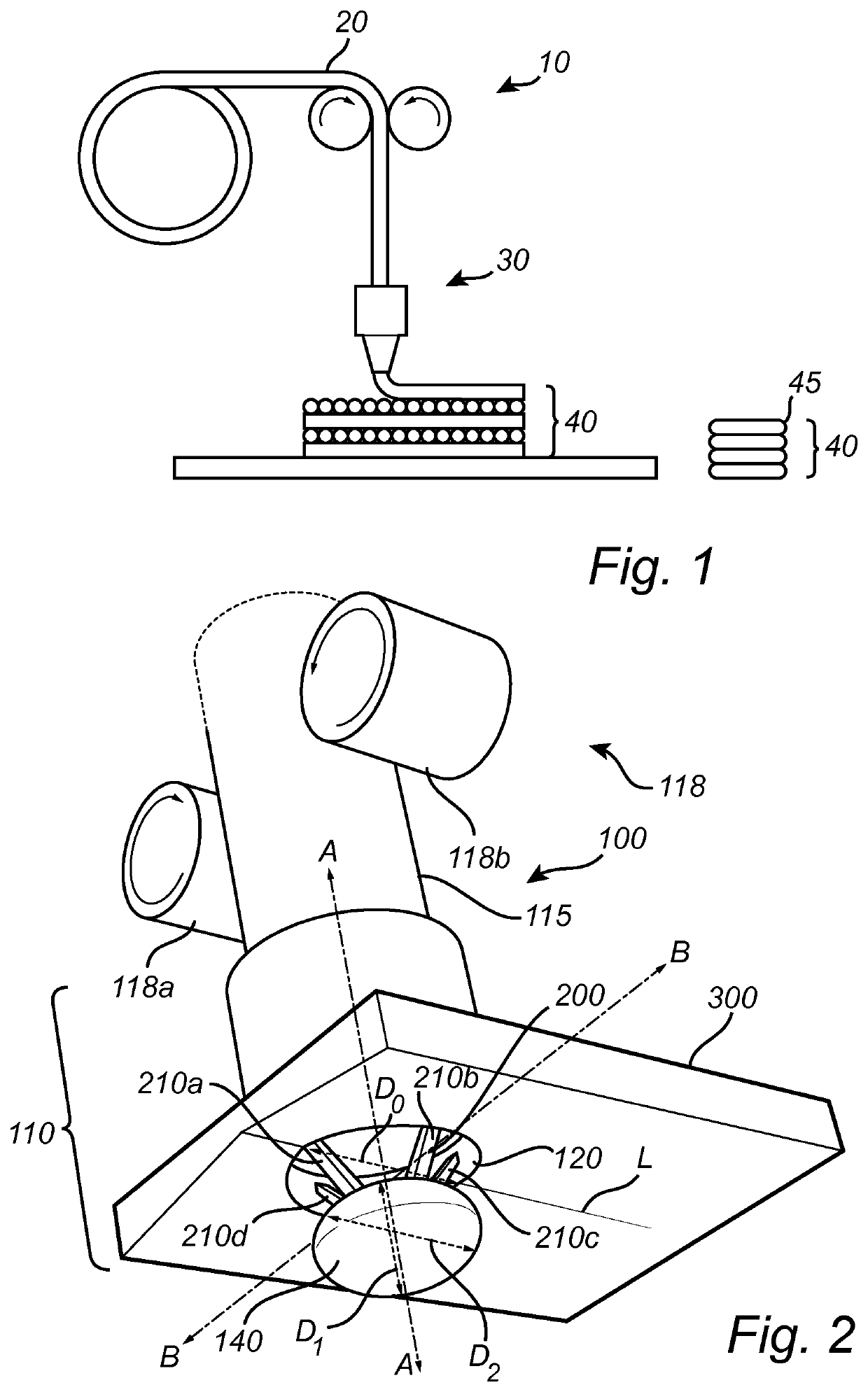
"d_n">[0037]FIG. 1 is a schematic view of a printer head 10 of a 3D-printing apparatus according to the prior art. The printer head 10 uses a printing material in form of a thermoplastic filament 20 which is fed to nozzle 30 for deposition. The filament 20 is heated to a temperature at which it may flow readily, and the nozzle 30 may deposit (extrude) the printing material in layers 40 to create a 3D object. 3D-printing apparatuses of this kind are relatively fast, cost-efficient and can be used for printing relatively complicated 3D objects.

[0038]During operation of the 3D-printing apparatus, the relatively hot printing material is pressed through the nozzle 30 of the printer head 10 and solidifies on a build-plate or on a previously solidified layer of printing material. Due to the laminar flow of the melted printing material, the layers 40 often comprise bulged or rounded edges 45, as schematically shown in FIG. 1. Consequently, the bulged layers 40 lead to a relatively rough sur...


PUM

PropertyMeasurementUnit
angleaaaaaaaaaa
diameteraaaaaaaaaa
shapeaaaaaaaaaa

Abstract

A printer head (100) for a 3D-printing apparatus, comprising a nozzle (110) arranged to extrude a printing material along a principal axis (A) of the nozzle. The nozzle comprises an opening (120) having a first area (130) for allowing a flow of printing material there through, and an element (140) arranged centrally with respect to the opening in a plane perpendicular to the principal axis of the nozzle. The element has a cross-sectional second area (150) parallel to the first area, wherein the second area, in a projection on the first area in a direction along the principal axis, is defined by the first area, such that the nozzle, during operation of the printer head, allows a flow of printing material through the opening and around the element.

Description

FIELD OF THE INVENTION[0001]The present invention generally relates to the field of 3D printing. More specifically, the present invention relates to a printer head for a 3D printing apparatus, and a method for controlling such a printer head.BACKGROUND OF THE INVENTION[0002]Additive manufacturing, sometimes also referred to as 3D printing, refers to processes used to synthesize a three-dimensional object. 3D printing is rapidly gaining popularity because of its ability to perform rapid prototyping without the need for assembly or molding techniques to form the desired article.[0003]By using a 3D printing apparatus, the article or object may be built in three dimensions in a number of printing steps that are usually controlled by a computer model. For example, a sliced 3D model of the object may be provided in which each slice is recreated by the 3D printing apparatus in a discrete printing step. The 3D printing apparatus may extrude successive layers of an extrudable material from a...

Claims


Application Information

Patent Timeline
Patent Type & Authority Applications(United States)
IPC IPC(8): B29C64/118B29C64/209
CPCB29C64/118B33Y30/00B29C64/209B33Y10/00B33Y70/00B29K2101/12
Inventor HIKMET, RIFAT ATA MUSTAFACHITTKA, UWE
Owner SIGNIFY HLDG BV
Why Eureka
Try Eureka