Eureka AIR delivers breakthrough ideas for toughest innovation challenges, trusted by R&D personnel around the world.

Projection objective and waveguide display device

Active Publication Date: 2021-05-27
DISPELIX OY
View PDF0 Cites 3 Cited by
  • Summary
  • Abstract
  • Description
  • Claims
  • Application Information

AI Technical Summary

Benefits of technology

The invention is a new type of projection objective that can be used to send light into a waveguide. This objective has a special design that makes it very efficient at expanding the image in two dimensions. The invention allows for a much smaller and more compact projection objective that produces a collimated beam of light. The optical configuration also results in a larger field of view and a more perpendicular beam of light, which improves the efficiency of the light engine.

Problems solved by technology

In addition, telecentricity of these objectives is typically not very high.
The mobile phone camera solutions are not as such applicable to the projection part of waveguide type displays and are in particular not capable of being used for expanding projector exit pupil along two dimensions in combination with diffractive gratings.

Method used


Image

  • Projection objective and waveguide display device
  • Projection objective and waveguide display device
  • Projection objective and waveguide display device

Examples


Embodiment Construction

[0026]In the following discussion, various embodiments of the invention are introduced that allow keeping the objective size small, incorporating sufficient back focal length to the design and enforcing the telecentricity condition on the edge field rays.

[0027]Relative referrals, such as “before”, “after”, “first” and “last”, unless otherwise apparent, are herein made with reference to the travel direction of light from the first plane (projector) towards the second plane (waveguide display). Optical element groups, optical elements therein and refractive surfaces are, however, numbered in the opposite order from the second plane towards the first plane.

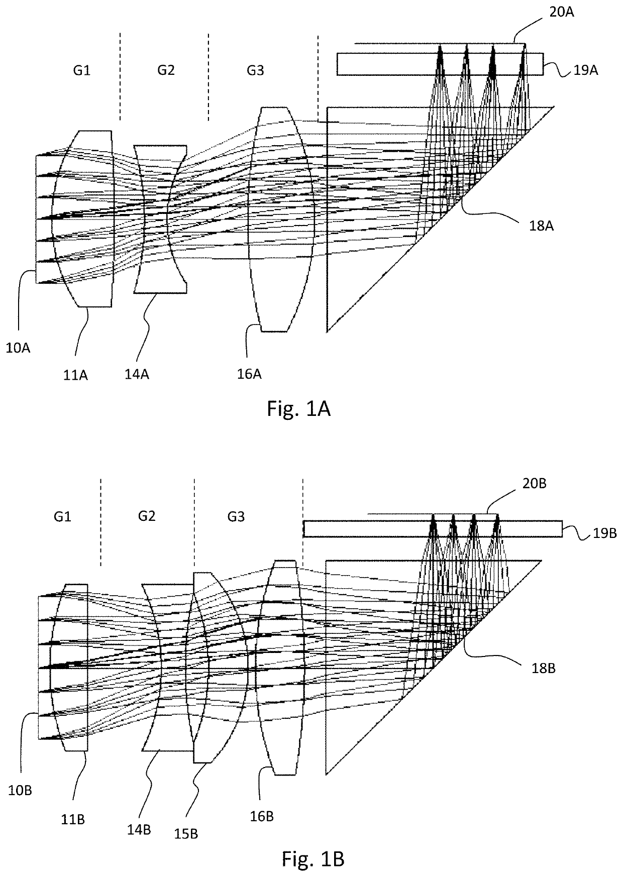
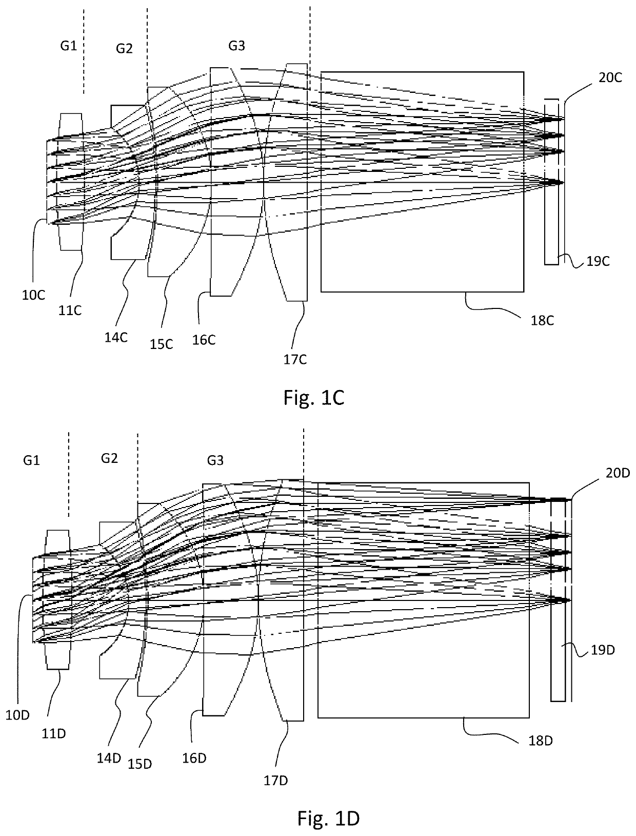
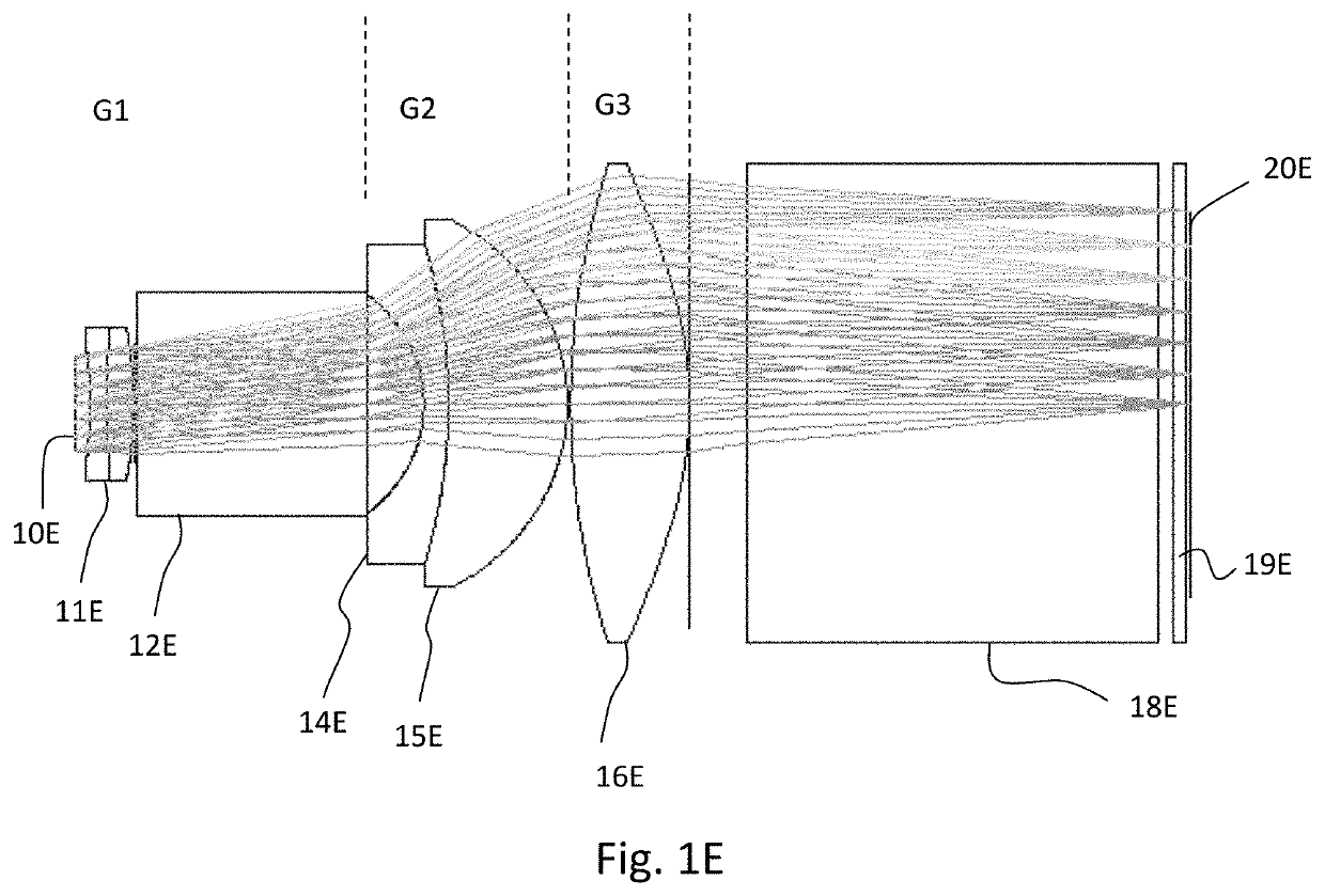
[0028]In embodiments of the present invention, the objective is divided into three groups, which may contain one or more optical elements, in particular lenses. The elements may or may not be aspherical. In FIGS. 1A1E, the three groups are denoted with G1, G2 and G3, starting from the second plane. The second plane is denoted with re...


PUM


Abstract

The invention concerns a projection objective and a waveguide display. The objective is adapted to project an image from a first plane to a second plane and comprises in order from the second plane a first optical element group having a positive effective focal length, a second optical element group placed between the first plane and the first optical element group and having a negative effective focal length, and a third optical element group placed between the first plane and the second optical element group and having a positive effective focal length. Counting from the second plane, the first refractive surface of the second optical element group is concave towards the second plane and the second refractive surface of the third optical element group is convex towards the first plane. The objective suits well for projecting images to diffractive optical displays.

Description

FIELD OF THE INVENTION[0001]The invention relates to projection objectives. In particular, the invention relates to a telecentric projection objective for augmented reality (AR) applications and the like.BACKGROUND OF THE INVENTION[0002]Recent interest in augmented reality applications and augmented reality systems has increased the number of different optical methods in achieving the overlap between projected image and the real background.[0003]A specific type of display used in AR systems is a waveguide type display, where light is coupled in to a piece of glass or polymer in an in-coupling region and the light propagates therein within the total internal reflection limit angle until it is coupled out from the light guide at an out-coupling region. Ray splitting at the out-coupling region can effectively expand the eye box of the system at the cost of brightness.[0004]Waveguide type displays can principally be split to two different groups. In the first group the projection object...

Claims


Application Information

Patent Timeline
IPC IPC(8): G02B13/16G02B13/00G02B9/30G02B27/01
CPCG02B13/16G02B13/006G02B27/0172G02B9/30G02B13/0035G02B27/0081G02B13/22G02B2027/0174G02B13/24G02B9/16G02B5/1814G02B6/0016G02B9/14G02B27/4272
Inventor AIKIO, MIKA
Owner DISPELIX OY
Why Eureka
Eureka Blog
Learn More