Surgical instruments for ocular surgery

a surgical instrument and ocular surgery technology, applied in the field of medical instruments, can solve the problems of requiring significant expertise to operate safely, unstable incisions, and long recovery times, and achieve the effects of reducing the risk of aspiration blockage, and reducing the risk of ocular surgery

Pending Publication Date: 2021-06-24
JOHNSON & JOHNSON SURGICAL VISION INC
View PDF0 Cites 0 Cited by
  • Summary
  • Abstract
  • Description
  • Claims
  • Application Information

AI Technical Summary

Benefits of technology

[0014]Thus, the disclosure may provide simpler and less expensive systems, apparatuses, and methods for performing cataract surgery. The apparatus, system and method may provide a surgical instrument for safe, controlled, and uncomplicated removal of the cataractous nucleus from the eye in its entirety, regardless of the maturity or hardness of the nucleus, while using a small eye incision size and with minimized risk of aspiration blockage-induced damage.

Problems solved by technology

Some of these methods require large incisions that are unstable and require prolonged recovery times. More current techniques generally require making much smaller incisions in the eye, and removing the cataract from the eye through this small incision.
Nevertheless, phacoemulsification is very expensive, and requires expensive and sophisticated equipment that demands significant expertise to operate safely.
Further, ultrasonic phacoemulsification can suffer impediments to optimal performance.
For example, cavitation bubbles which result from ultrasonic activity in a liquid may adversely impact phacoemulsification results.
Corneal burns can also occur due to the friction of the phacoemulsification tip and the eye incision, which friction results from the ultrasonic vibration of the phacoemulsification tip.
That is, corneal burns may result from the maintaining of contact between the emulsifying instrument as it vibrates and the cornea.
However, because such methods typically lack an ability to maintain position, and lack the aspiration and irrigation elements typical in phacoemulsification, maintenance of continued contact between the cutting element and cataract becomes very difficult, and fragments of the cataract are overly free to float about inside the eye in a variably pressurized environment, thereby complicating cataract removal and increasing the likelihood of damage.
To the extent pressure differential vacuum control is included in such embodiments to aid in the removal of macerated tissue and aid in stabilizing the cataract, the arrangement often results in inelegant communication between the screw, the aspiration system and any irrigation system, particularly if particles become stuck in the aspiration system.
The condition wherein a particle gets stuck, or “occludes”, the aspiration during phacoemulsification can cause either sudden increases or drops in eye pressure, or significant fluid flow with concomitant turbulence inside the eye, which instances have great potential for intraocular damage.
Upon breaking of the occlusion, stored energy in the tubing causes a rapid surge flow from the patient's eye, which can cause adverse effects to the structures within the eye.
While mini-surges may happen hundreds of times during a typical phacoemulsification surgery, a major POS event may only happen occasionally, but with very significant adverse effects to the patient.

Method used


Image

  • Surgical instruments for ocular surgery
  • Surgical instruments for ocular surgery
  • Surgical instruments for ocular surgery

Examples


Embodiment Construction

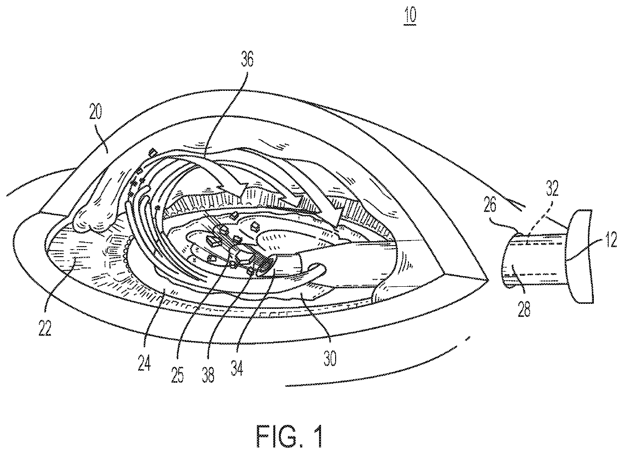
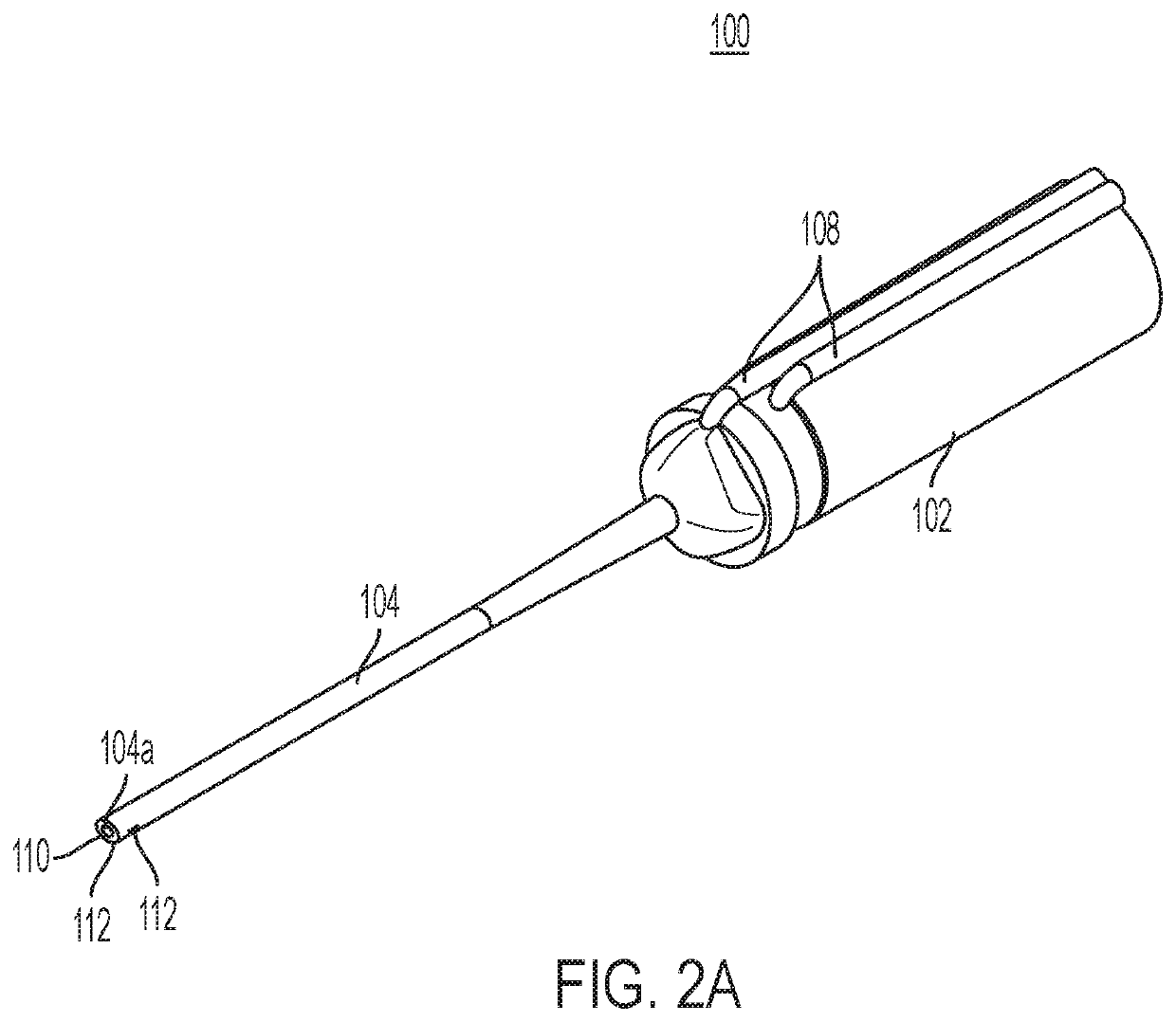
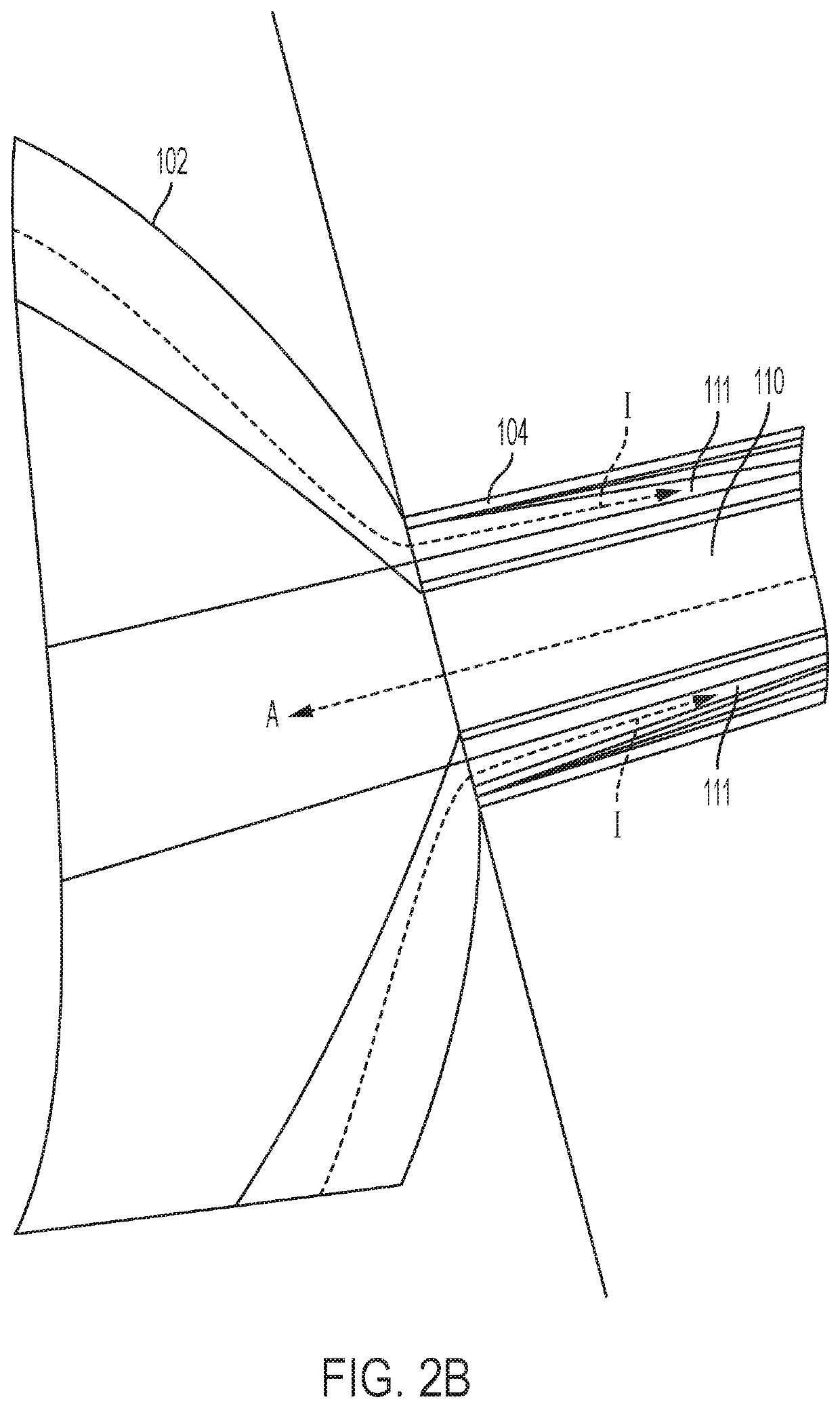
[0020]The figures and descriptions provided herein may be simplified to illustrate aspects of the described embodiments that are relevant for a clear understanding of the herein disclosed processes, machines, manufactures, and / or compositions of matter, while eliminating for the purpose of clarity other aspects that may be found in typical surgical, and particularly ophthalmic surgical, devices, systems, and methods. Those of ordinary skill may thus recognize that other elements and / or steps may be desirable or necessary to implement the devices, systems, and methods described herein. Because such elements and steps are well known in the art, and because they do not facilitate a better understanding of the disclosed embodiments, a discussion of such elements and steps may not be provided herein. However, the present disclosure is deemed to inherently include all such elements, variations, and modifications to the described aspects that would be known to those of ordinary skill in th...


PUM


Abstract

A handpiece for ocular surgery that includes a handle having at least inlets for irrigation and aspiration; a sleeve extending distally from a first end of the handle, wherein the sleeve comprises a bore extending a length of the sleeve along a central axis of the sleeve, and includes at least one port suitable to deliver irrigation from the irrigation inlet substantially distal from the first end of the handle; the aspiration being provided between an aspiration inlet and a distal bore port; a motor coupled with a second end of the handle and having a shaft; and an auger associated with the shaft, and extending at least partially through an interior portion of the handle between the second and the first ends and extending along the length of the sleeve, wherein a tip of the auger distal to the shaft is advanced by actuation of the motor.

Description

CROSS REFERENCE TO RELATED APPLICATIONS[0001]This application claims the benefit under 35 U.S.C. § 119(e) of U.S. Provisional Patent Application No. 62 / 702,775, filed Jul. 24, 2018, which is incorporated herein by reference in its entirety.FIELD OF THE DISCLOSURE[0002]The disclosure relates to medical instruments, and more specifically, to surgical instruments for performing ocular surgery.BACKGROUND[0003]A cataract is a type of visual impairment, and is defined as an opacity in the crystalline lens of the eye, which interferes with vision. Once visual function has been compromised by a cataract, surgery is performed to remove the opaque lens in order to restore proper eye function. Cataracts are the most prevalent disabling eye disease worldwide.[0004]Many methods of cataract extraction have been developed. Some of these methods require large incisions that are unstable and require prolonged recovery times. More current techniques generally require making much smaller incisions in ...

Claims


Application Information

Patent Timeline
Patent Type & Authority Applications(United States)
IPC IPC(8): A61F9/007
CPCA61F9/00754A61F9/00736A61F9/00763
Inventor HICKEY, LAUREN M.
Owner JOHNSON & JOHNSON SURGICAL VISION INC
Why Eureka
Try Eureka