Autoclave molding apparatus

Inactive Publication Date: 2021-06-24
ASHIDA MFG
View PDF10 Cites 0 Cited by
  • Summary
  • Abstract
  • Description
  • Claims
  • Application Information

AI Technical Summary

Benefits of technology

The invention is for an autoclave molding apparatus that can effectively prevent a composite material from overheating during the curing process using steam. This results in a stronger and more uniform composite material molded article.

Problems solved by technology

However, since heat is transferred through the gas in both the heating process and the cooling process, these processes take a lot of time, which results in a decrease in productivity.
This is a problem to be solved.

Method used


Image

  • Autoclave molding apparatus
  • Autoclave molding apparatus
  • Autoclave molding apparatus

Examples


second embodiment

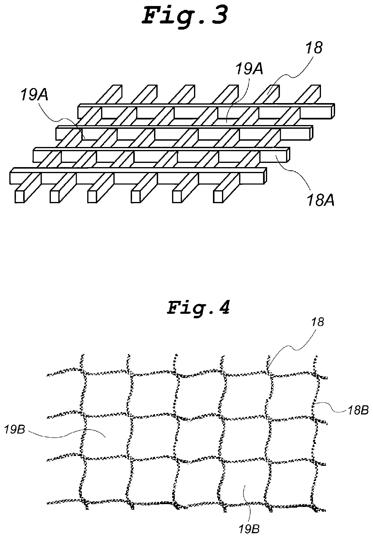
[0041]FIG. 4 is a schematic view of the condensed water holder 18 according to another embodiment (a second embodiment) of the present invention. This condensed water holder 18 is made of a mesh material 18B obtained by knitting fibers of a heat-resistant fibrous material capable of holding condensed water, for example, a synthetic fiber such as polyester or nylon, a hydrophilic natural fiber such as cotton or linen, or a glass fiber. Such a mesh material has openings 19B through which steam can pass easily. The amount of supplied water can be easily controlled by changing the diameter of the fibers of the fibrous material, for example.

third embodiment

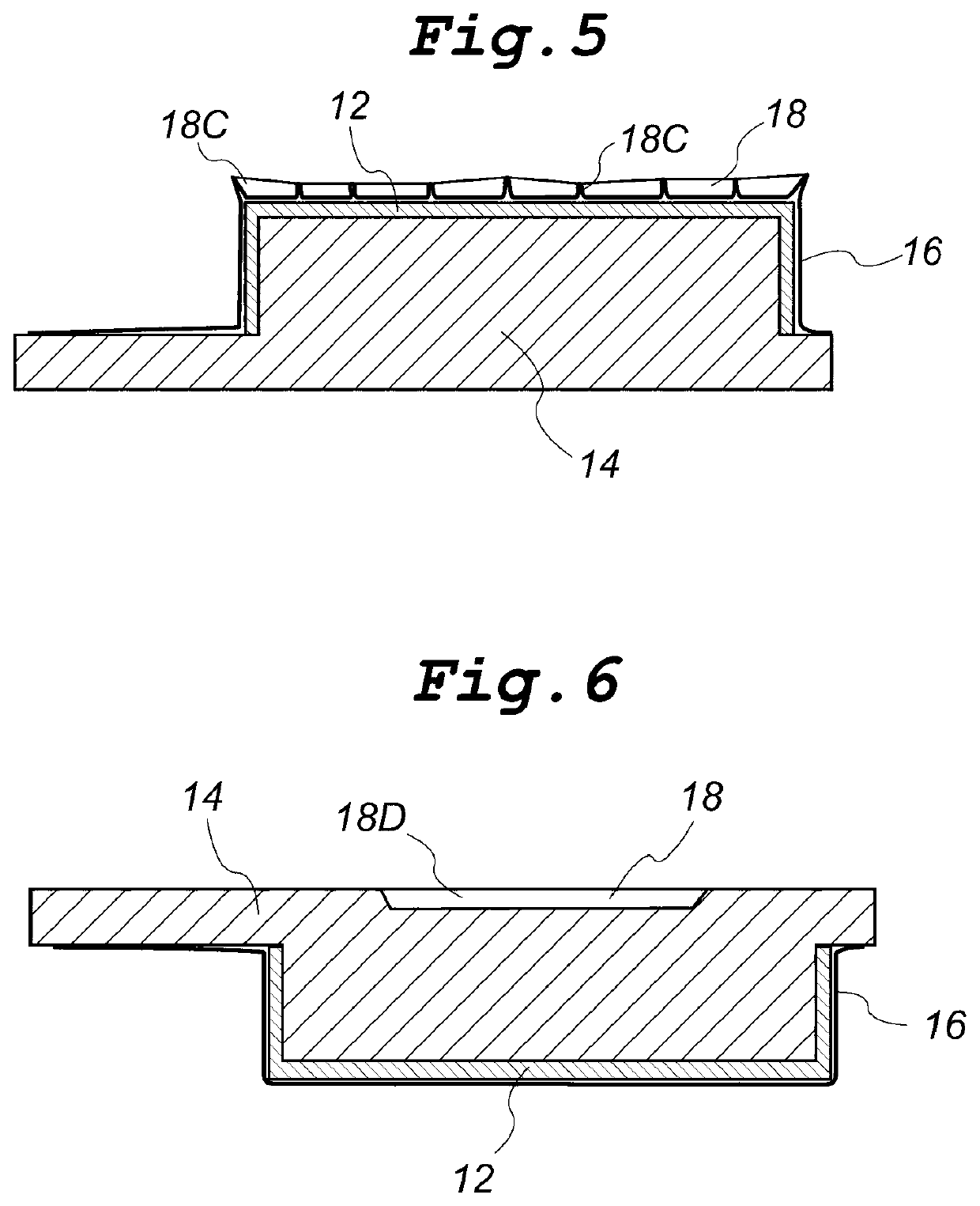
[0042]FIG. 5 is a cross-sectional view of the condensed water holder 18 according to another embodiment (a third embodiment) of the present invention.

[0043]The composite material 12 made of a fibrous base material impregnated with a thermosetting resin matrix is sealed together with a molding tool 14 in the vacuum bag 16. The size of the vacuum bag 16 used is slightly larger than that of the assembly covered by the bag 16 so that the bag 16 can enclose the resulting molded article having a shape conforming to the shape of the molding tool. Therefore, wrinkles 18C are formed on the surface of the vacuum bag 16 and prevent the inner surface of the vacuum bag 16 from being closely contact with the surface of the composite material 12 and the surface of the molding tool 14. When the vacuum bag 16 is sealed, the wrinkles 18C are formed to have a shape for capturing the condensed water. The height of the wrinkles is determined based on the amount of water to be held.

[0044]The condensed wa...

fourth embodiment

[0045]FIG. 6 is a cross-sectional view of the condensed water holder 18 according to another embodiment (a fourth embodiment) of the present invention.

[0046]The composite material 12 made of a fibrous base material impregnated with a thermosetting resin matrix is sealed together with a molding tool 14 in the vacuum bag 16. A recessed portion 18D to serve as the condensed water holder 18 is preformed on a surface (top surface) of the molding tool 14 opposite to a surface on which the composite material 12 is placed. In the present embodiment, the assembly is disposed such that the surface of the composite material 12 faces downward in the gravity direction.

[0047]The condensed water generated during heating is accumulated in the recessed portion 18D. When the amount of the condensed water exceeds a predetermined value, it overflows from the recessed portion 18D. Therefore, the thickness of the condensed water is not large and thus the high efficiency of heat transfer during condensati...


PUM

PropertyMeasurementUnit
Temperatureaaaaaaaaaa
Strengthaaaaaaaaaa

Abstract

The present invention relates to an autoclave molding apparatus for use in molding a composite material composed of a fibrous base material and a matrix and sealed together with a molding tool in a vacuum bag, using steam for heating and compressing the composite material. The present invention provides an autoclave molding apparatus capable of effectively reducing the overshoot of the temperature of the composite material caused by poor dissipation of curing heat in a curing process and thereby capable of producing a composite material molded article having uniform and sufficient strength. More specifically, an autoclave molding apparatus of the present invention is characterized in that a condensed water holder(s) configured to hold condensed water generated by heating is mounted on at least a portion of the vacuum bag and / or at least a portion of the molding tool.

Description

TECHNICAL FIELD[0001]The present invention relates to an autoclave molding apparatus for use in forming composite material molded articles used in aircraft, automobile and other general industries.BACKGROUND ART[0002]A molded article having a desired cross-sectional shape can be obtained by a known technique, in which sheets of prepreg, i.e., a composite material produced by impregnating a reinforcing material, such as carbon fiber, aramid fiber, or glass fiber, with a thermosetting resin matrix, such as epoxy resin or phenol resin, are heated and compression-molded. Carbon fiber and glass fiber have high elasticity. Therefore, these fibers are formed into thin fiber sheets, which are laminated such that the fibers in the adjacent sheets are oriented in different directions to obtain a composite material. Since lightweight and strong products can be obtained from such composite materials, these materials are widely used in aircraft, automobile and other general industries. A composi...

Claims


Application Information

Patent Timeline
IPC IPC(8): B01J3/04B29C35/04B29C43/12B29C70/44
CPCB01J3/04B29C70/44B29C43/12B29C35/041B29C35/049B29C35/0227B29C43/52B30B11/001B30B11/002
Inventor YAMAMOTO, YOSHIAKIASHIDA, TAKESHI
Owner ASHIDA MFG
Why Eureka
Try Eureka