Drilling device with optimized actuation

a drilling device and actuation technology, applied in the direction of boring/drilling equipment, portable power-driven tools, electrical equipment, etc., can solve the problems of increasing the total cost of manufacturing of aircraft, sequencing increases the total cost of drilling operations, and complicated cutting parameters

Inactive Publication Date: 2021-06-24
ETAB GEORRENAULT
View PDF0 Cites 0 Cited by
  • Summary
  • Abstract
  • Description
  • Claims
  • Application Information

AI Technical Summary

Benefits of technology

[0041]According to one possible characteristic, a device according to an exemplary embodiment of the invention comprises means for determining the position of said trigger, said means for determining comprising a first Hall effect sensor and a detection magnet fixedly attached to said trigger.
[0042]According to one possible characteristic, said means for determining the position of said trigger comprise a second Hall effect sensor, said first and second sensors being distant from each other along the trajectory of movement of said trigger
[0043]According to one possible characteristic, said first Hall effect sensor is of the analog type and said second Hall effect sensor is of a digital or analog type.

Problems solved by technology

A first challenge results from the fact that aircraft today are constituted by numerous materials, such as for example carbon composite materials, aluminum or aluminum-lithium alloy, titanium and steel.
These different materials have different cutting conditions and their stacking in aircraft structures complicates the cutting parameters.
This sequencing increases the total cost of manufacture of the aircraft, whether it is because of the multiplicity of drilling operations, or because of the increased precision of positioning of the holes on the various elements to be drilled as well as the time needed to handle the parts to be drilled.
A second challenge results from the fact that a large number of drilling operations are carried out by hand.
A portion of these drilling operations is carried out with automatic drilling units (fixed to drilling templates or patterns that fulfil the template function) but there is still a large amount of drilling carried out by hand-held drills because of space requirements or the cost of tools.
A third challenge results from the fact that the competitive development of the aeronautical sector imposes new requirements in terms of production rates and an improvement of productivity.
The operation of drilling by hand is a complex one that depends greatly on the qualifications and competence of the operator and that can entail numerous problems of non-compliance with requisite quality (i.e. sub-standard maintenance).
These instances of sub-standard maintenance can be because of problems of surface conditions, burrs, scaling, delamination, drifts in values of diameter, shapes and orientation, etc.
These factors lead to a reduction of productivity and major costs (it costs, on average, €1,200 to redo a hole, and this amounts to costs of millions of Euros per year).
The issue today therefore is to be able to adjust the cutting parameters as efficiently as possible for each specific drilling phase.
This choice thus penalizes productivity and entails lower quality for a material that is not drilled with the optimal parameters.
Besides, the air nozzle of the drill can also be cumbersome when making certain holes that have complicated accessibility.
Drilling units with controlled cutting parameters do not meet the need for portable tools.
These are tools intended to be fixed to a frame during the drilling action and are therefore not easy to handle.
The technical limits of the prior art for these pneumatic and electric drills therefore mean that it is not possible to respond to developments in the requirements of productivity and of flexibility of the tools for production in the aeronautics sector.

Method used


Image

  • Drilling device with optimized actuation
  • Drilling device with optimized actuation
  • Drilling device with optimized actuation

Examples


Embodiment Construction

[0060]5.1. Architecture

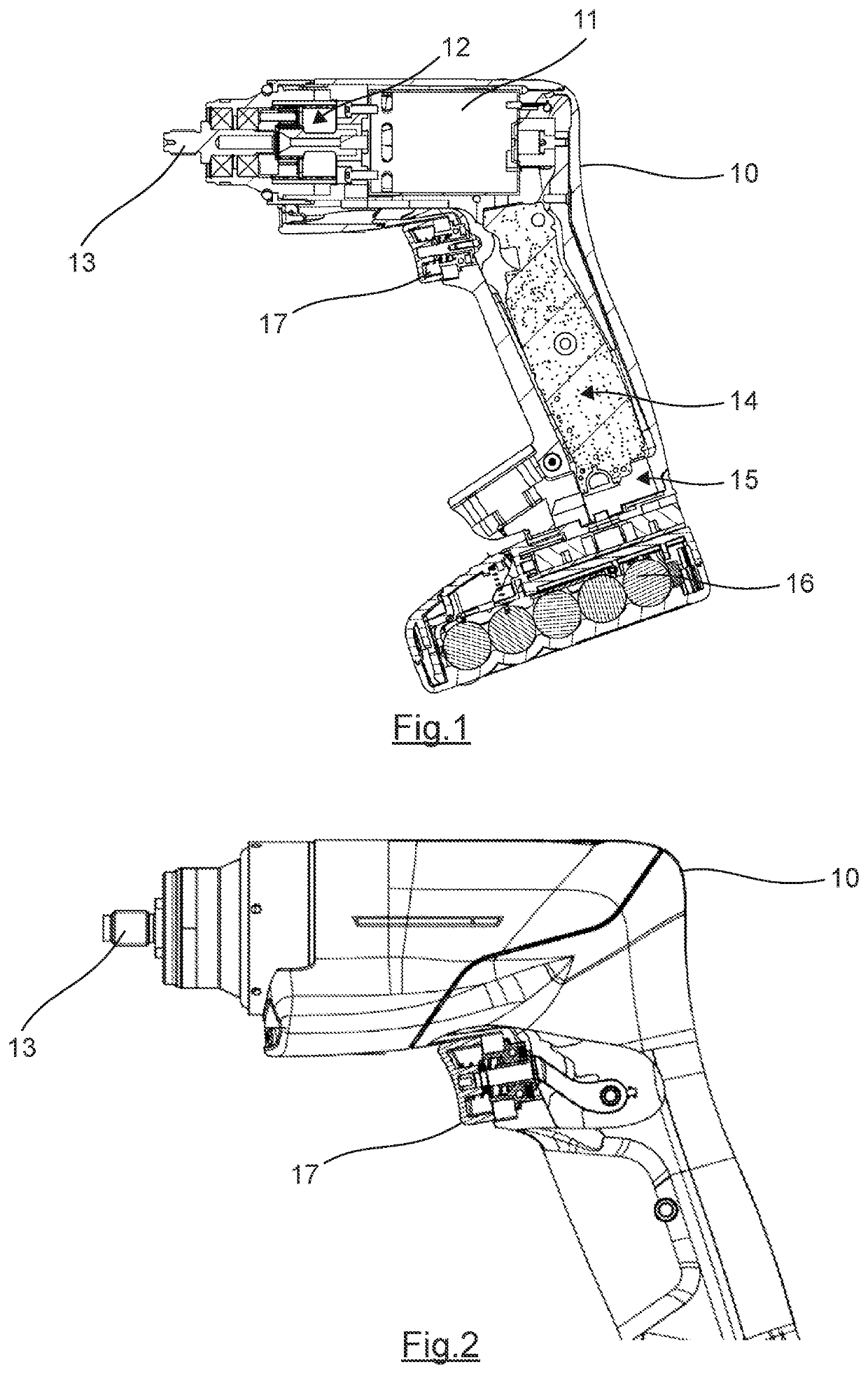
[0061]Referring to FIGS. 1 to 13, we present an example of a drilling device according to an exemplary embodiment of the invention. It could also be a screw driving device capable of performing the screw driving function or the screwing and unscrewing functions.

[0062]As represented, such a device comprises a casing 10. This casing is herein of the pistol grip type (the axis of the grip forms a non-zero angle with the axis of the rotation of the terminal member). It could also be a longitudinal casing of which the axis of the grip is parallel with or coincides with the axis of rotation of the terminal member or it could be any other type of casing.

[0063]This casing 10 houses an electric motor 11. It is preferably a permanent magnet synchronous motor. It could however be any other type of electric motor.

[0064]The output shaft of the motor is connected to the input of a transmission 12, the output of which is connected to a terminal member 13 can be driven in rot...


PUM

PropertyMeasurementUnit
rotation frequencyaaaaaaaaaa
magnetic attractionaaaaaaaaaa
distanceaaaaaaaaaa

Abstract

A portable drilling device or screw driving device, including: an electric motor; an autonomous or wired electric supply to the motor; an actuating trigger; a controller, which commands the motor as a function of the position of the trigger; the trigger being mobile between at least: a resting position in which the motor is at a stop; a position of total actuation in which the motor is driven by the controller according to a first predetermined rotation frequency; wherein the trigger can take a predetermined intermediate position is situated between the resting and actuating positions and the motor being driven by the controller according to a second predetermined rotation frequency. An elastic return counters movement of the trigger from the resting position towards the position of total actuation, and a first fixed magnetic attraction counters movement of the trigger between the intermediate position and the position of total actuation.

Description

1. FIELD OF THE INVENTION[0001]The field of the invention is that of portable drilling tools.[0002]The invention relates more particularly to the trigger for actuating such tools.2. PRIOR ART[0003]Portable drilling tools are commonly used in various fields such as, for example, the aeronautics industry.[0004]Aeronautical production has to cope with three main technical challenges.[0005]A first challenge results from the fact that aircraft today are constituted by numerous materials, such as for example carbon composite materials, aluminum or aluminum-lithium alloy, titanium and steel. These different materials have different cutting conditions and their stacking in aircraft structures complicates the cutting parameters. Thus, to make sure that a high level of quality of the finished parts is maintained, a drilling operation must sometimes be sub-divided into several operations. This sequencing increases the total cost of manufacture of the aircraft, whether it is because of the mult...

Claims


Application Information

Patent Timeline
Patent Type & Authority Applications(United States)
IPC IPC(8): B25B21/00B25F5/02
CPCB25B21/008B25F5/02B23B45/02H03K17/97B23B2260/10B23B2260/136H03K17/9517
Inventor POIRIER, KEVIN
Owner ETAB GEORRENAULT
Why Eureka
Try Eureka