Additive manufacturing system and method using robotic arms

Pending Publication Date: 2021-06-24
THE BOEING CO
View PDF2 Cites 4 Cited by
  • Summary
  • Abstract
  • Description
  • Claims
  • Application Information

AI Technical Summary

Benefits of technology

[0004]In one or more embodiments of the present disclosure, an additive manufacturing system is provided that includes a first robotic arm and a print head with a nozzle. The first robotic arm is configured to hold a build part during a build process. The print head is configured to deposit source material layer by layer during the build process to construct the build part. The first robotic arm is configured to reorient the build part relative to the print head during the build process to modify an angle of a surface layer of the build part relative to the print head.
[0005]In one or more embodiments of the present disclosure, a method for additive manufacturing using robotic arms is provided that includes controlling a first robotic arm to hold a build part suspended above a floor. The method includes depositing source material layer by layer on the build part from a nozzle of a print head to construct the build part during a build process. The method also includes controlling the first robotic arm to move the build part relative to the pr

Problems solved by technology

The supports are removed from the build part after the additive manufacturing build process, and the removal process can be costly, difficult, time intensive, and/or labor intensive.
For example, the supports may need to be cut and grinded away from the surfaces of the build part, which can be especially di

Method used


Image

  • Additive manufacturing system and method using robotic arms
  • Additive manufacturing system and method using robotic arms
  • Additive manufacturing system and method using robotic arms

Examples


Example

[0020]The foregoing summary, as well as the following detailed description of certain embodiments will be better understood when read in conjunction with the appended drawings. As used herein, an element or step recited in the singular and preceded by the word “a” or “an” should be understood as not necessarily excluding the plural of the elements or steps. Further, references to “one embodiment” are not intended to be interpreted as excluding the existence of additional embodiments that also incorporate the recited features. Moreover, unless explicitly stated to the contrary, embodiments “comprising” or “having” an element or a plurality of elements having a particular property may include additional elements not having that property.

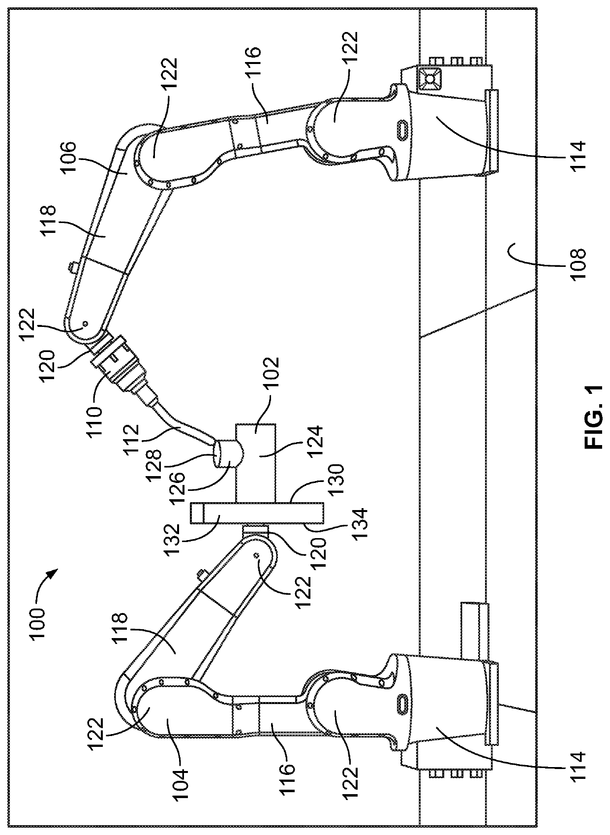
[0021]In consideration of the cost, time, and labor of performing finishing treatments after the build process to grind away extraneous material, such as supports, to polish various surfaces, and the like, there are advantages in techniques for additiv...


PUM

PropertyMeasurementUnit
Angleaaaaaaaaaa

Abstract

An additive manufacturing system includes a first robotic arm and a print head with a nozzle. The first robotic arm is configured to hold a build part during a build process. The print head is configured to deposit source material layer by layer during the build process to construct the build part. The first robotic arm is configured to reorient the build part relative to the print head during the build process to modify an angle of a surface layer of the build part relative to the print head.

Description

FIELD OF THE DISCLOSURE[0001]Embodiments of the present disclosure generally relate to additive manufacturing of three-dimensional build parts.BACKGROUND[0002]Additive manufacturing refers to any process for manufacturing a three-dimensional build part in which successive layers of material are deposited under computerized control. The deposited layers fuse to pre-existing portions of the build part by applying heat, a laser beam, or the like. The size and shape of the build part can be based on a three-dimensional computer model or another electronic data source. Additive manufacturing can be used to fabricate objects that have complex structures and shapes. Additive manufacturing techniques for fabricating metal build parts can allow greater design freedom and yield more precise and repeatable finished products than conventional metal manufacturing techniques, such as die-casting, extruding, milling, and the like. Relative to conventional metal manufacturing techniques, such as mi...

Claims


Application Information

Patent Timeline
IPC IPC(8): B29C64/379B29C64/209B29C64/245B33Y10/00B33Y30/00
CPCB29C64/379B29C64/209B33Y30/00B33Y10/00B29C64/245B22F12/53B22F12/37B22F10/66B22F10/18B29C64/227B29C64/118Y02P10/25
Inventor CARDON, LISA A.
Owner THE BOEING CO
Why Eureka
Try Eureka