
Circuit Test Device and Method

a test device and circuit technology, applied in continuity testing, measurement devices, instruments, etc., can solve the problems of increasing the risk of user error for conventional devices and methods, and achieve the effects of reliable and simple process, short timeframe, and accurate results

Active Publication Date: 2021-06-24
THE UNITED STATES OF AMERICA AS REPRESENTED BY THE FEDERAL BUREAU OF INVESTIGATION DEPT OF JUSTICE
View PDF0 Cites 0 Cited by
  • Summary
  • Abstract
  • Description
  • Claims
  • Application Information

AI Technical Summary

Benefits of technology

The patent describes a device that can safely determine if two points in a circuit have electrical continuity or connectivity. This is done by measuring voltage and detecting test signals under specific conditions. The device is useful for assessing various circuit conditions, including checking the integrity of wires or the electrical relationships between wires. It is simple to use, reliable, and can provide accurate results in a shorter time frame compared to other known devices. The device can be used in field settings where distractions, pressure, and time constraints may increase the risk of user-error for conventional devices and methods.

Problems solved by technology

The devices and methods provided herein are simple to use and reliable, which is important during use in the field, where distractions, pressure and time constraints all contribute to an increased risk of user-error for conventional devices and methods.

Method used


Image

  • Circuit Test Device and Method
  • Circuit Test Device and Method
  • Circuit Test Device and Method

Examples


example 1

rformance

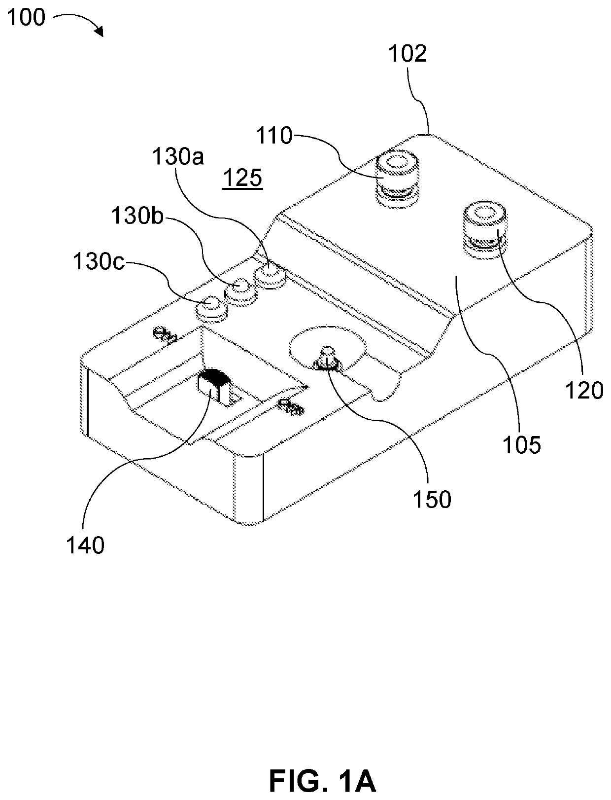
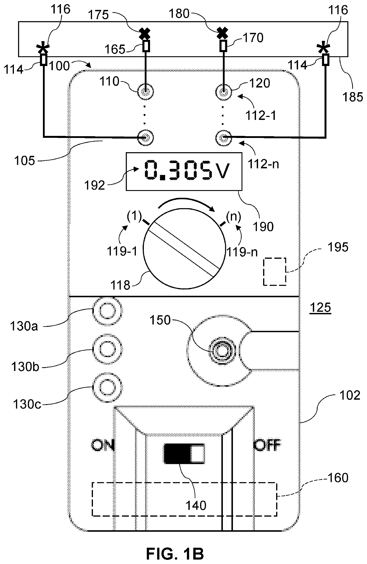
[0066]FIG. 5 is a flow chart of a process (500) of a use case for performance of the method (400) shown in FIG. 4 according to an embodiment of the disclosure. At a process (500) block (510), the device (100) user connects the first (165) and second (170) probes to the first pair (112-1) of terminals (110 and 120), and then connects the probes (110 and 120) across a CUT, such as a CUT including an explosive initiator of IED switch in the CUT 185. Additionally, or instead of, being performed by a human device (100) and / or circuit (200) user, block (510) may be performed by an autonomous, semi-autonomous, or remotely-controlled robot.

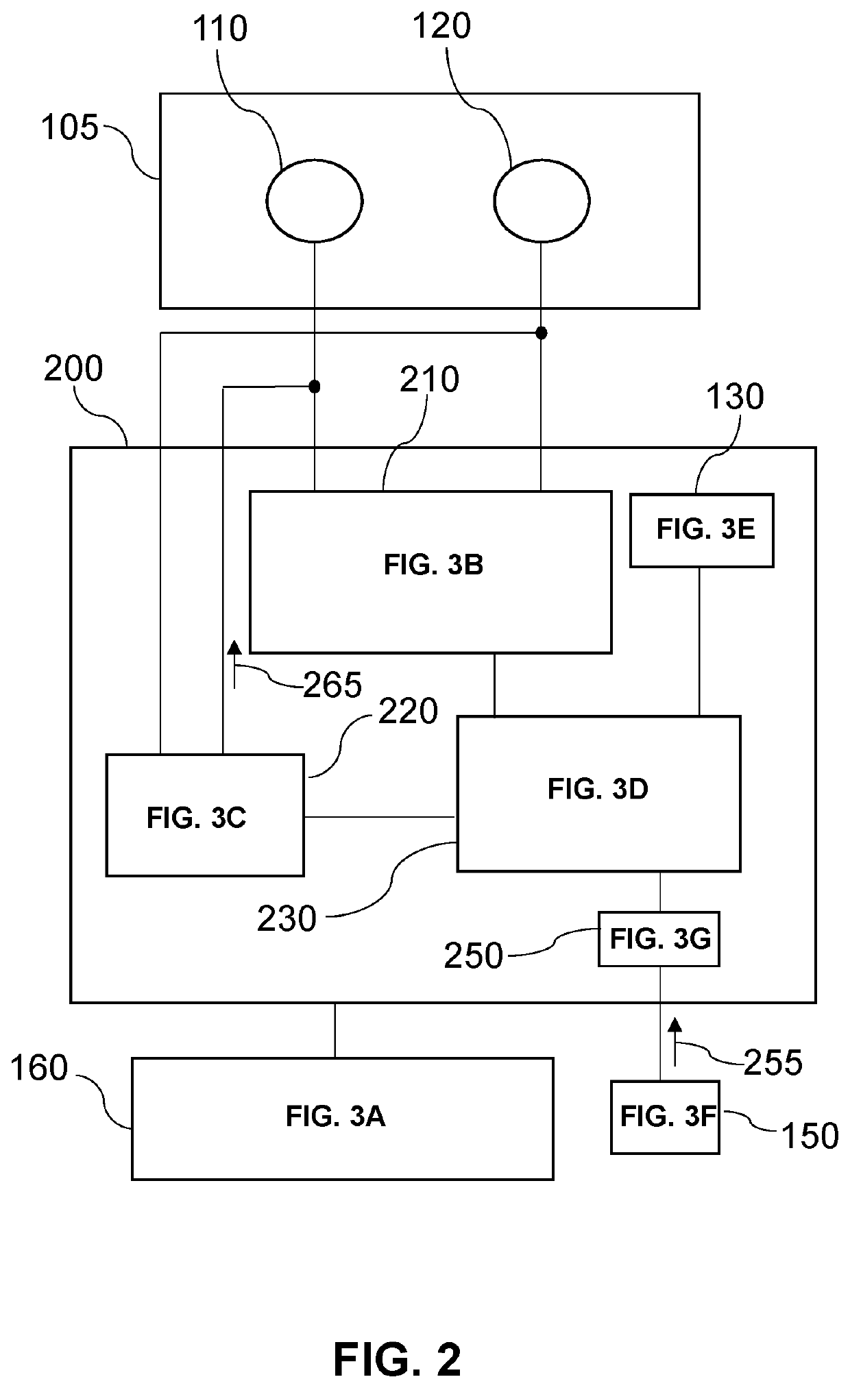
[0067]With the master power switch (140) in the on position, at process (500) blocks (520 and 530), differential voltage circuit (212) receives signals (511 and 513) from the probes (110 and 120, respectively). For purposes of this process (500) use case, the first terminal (110) is a passive reference / receiver circuit (224) input terminal and th...

example 2

ous Continuity Assessment

[0071]Referring to FIG. 1B, where the number (n) of pairs of terminals is 4, for instance, the device (100) may employ up to 8 probes to analyze up to 8 conductor points at a time in the CUT(s) (185) using method (400). In this use case example, with the 4 terminal pairs arranged in a first column (e.g., terminals 1-a, 2-a, 3-a and 4-a) and a second column (e.g., terminals 1-b, 2-b, 3-b and 4-b), and with only the terminals of the first column configured for transmitting (420) the test signal (265), up to 16 combinations of voltages and connection states between the 8 conductor points may be assessed at a time in method (400), as shown in the table below.

Circuit State Combinations (n = 4)Col. 1Col. 21-a2-a3-a4-a1-b- 1 -- 5 - - 9 -- 13 -2-b- 2 -- 6 -- 10 -- 14 -3-b- 3 -- 7 -- 11 -- 15 -4-b- 4 -- 8 -- 12 -- 16 -

[0072]For each of the 16 test combinations (e.g., “—1—”, . . . , “—16—”), the controller (234) orchestrates any or all of the above described steps of ...

example 3

l Device Check

[0076]To provide additional reassurance of device functionality ahead of use, various components may be incorporated into any of the methods and systems provided herein. For example, a power indicator light may be provided on the housing to indicate that the device is on and under power. Similarly, a low-power light may be used to indicate when it is time to replace the power source (e.g., battery).

[0077]Another component may be used to implement a process that verifies the device is performing properly (e.g., a “bump test”). Preferably, the bump test confirms there will be a proper output signal reflecting electrical continuity or discontinuity conditions, including for the various V conditions relative to Vlow and Vhigh. Accordingly, provided herein is a test block having a power source, circuit and a slider switch that is a functional substitute to reflect conditions of a CUT. The test block is connected to the device probes with the slider switch reflecting a high ...


PUM

PropertyMeasurementUnit
input impedanceaaaaaaaaaa
resistanceaaaaaaaaaa

Abstract

Circuit test devices and methods are provided. The method includes measuring a voltage between first and second conductor points (CPs) of a circuit under test (CUT), and determining if the measured voltage is less than a low voltage threshold value (LVTV) indicative of electrical continuity (EC) between the first and second CPs. In response to determining that the measured voltage is less than the LVTV, the method includes: transmitting a test signal (TS) to the first or second CP, and determining if the test signal is received after being transmitted. In response to determining that the TS is received, a presence of EC between the first and second conductor points is reported, and in response to determining that the TS is not received, absence of EC between the first and second CPs, or a lack of electrical contact between the VMC and the first and / or second CP(s), is reported.

Description

CROSS-REFERENCE TO RELATED APPLICATIONS[0001]This application claims the benefit of and priority to U.S. Provisional Patent Application No. 62 / 951,495 filed Dec. 20, 2019, which is specifically incorporated by reference in its entirety to the extent not inconsistent herewith.STATEMENT OF GOVERNMENT INTEREST[0002]The inventions described herein were invented by employees of the United States Government and thus, may be manufactured and used by or for the U.S. Government for governmental purposes without the payment of royalties.TECHNICAL FIELD[0003]Provided herein is technology related to circuit test devices and methods, and more particularly to devices, systems and methods that assess electrical continuity and circuit state in circuits under test (CUTs).BACKGROUND[0004]Checking continuity is a common function in explosives demolition and in CounterIED (C-IED) bomb disposal operations to verify circuit connections are intact. Also, determining the integrity of an electrical connecti...

Claims


Application Information

Patent Timeline
Patent Type & Authority Applications(United States)
IPC IPC(8): G01R19/165G01R31/54G01R31/58
CPCG01R19/16504G01R31/54G01R31/3277G01R19/16528G01R31/58
Inventor VABNICK, IAN B.MALONE, MICHAEL
Owner THE UNITED STATES OF AMERICA AS REPRESENTED BY THE FEDERAL BUREAU OF INVESTIGATION DEPT OF JUSTICE
Learn More