
Display device including see-through area for camera

a display device and see-through area technology, applied in the field of display devices, can solve the problems of decreased pixel area and increased non-pixel area, and achieve the effects of reducing the size of non-pixel area, improving transmittance, and suppressing the permeation of moisture into organic materials

Active Publication Date: 2021-06-24
LG DISPLAY CO LTD
View PDF21 Cites 3 Cited by
  • Summary
  • Abstract
  • Description
  • Claims
  • Application Information

AI Technical Summary

Benefits of technology

This patent is about improving the quality of a camera in a display device by reducing the impact on the image caused by neighboring pixels. The inventors have discovered that if the camera area overlaps with the display, the camera quality may be degraded. To solve this issue, the patent discusses a display device that minimizes the impact on the camera while also increasing the transparency of the camera area. By sealing the camera area and reducing the size of non-pixel areas, the device can improve image quality and prevent moisture and oxygen from affecting the organic light emitting elements in the display. Additionally, the patent mentions that the camera area may also have a touch function and improved transparency.

Problems solved by technology

The inventors of the present disclosure realized that conventional display devices have a problem in that a non-pixel area is increased and a pixel area is decreased due to the camera, the speaker, the sensor and the like being disposed in the non-pixel area outside the pixel area of the display device.
However, the inventors of the present disclosure have recognized that if a through-hole is formed in the display device to improve the transmittance of the see-through area for camera, moisture may permeate into pixels around the see-through area for camera, which may cause defects.

Method used


Image

  • Display device including see-through area for camera
  • Display device including see-through area for camera
  • Display device including see-through area for camera

Examples


Embodiment Construction

[0037]Advantages and characteristics of the present disclosure and a method of achieving the advantages and characteristics will be clear by referring to embodiments described below in detail together with the accompanying drawings. However, the present disclosure is not limited to the embodiments disclosed herein but will be implemented in various forms. The embodiments are provided by way of example only so that those skilled in the art can fully understand the disclosures of the present disclosure and the scope of the present disclosure.

[0038]The shapes, sizes, ratios, angles, numbers, and the like illustrated in the accompanying drawings for describing the embodiments of the present disclosure are merely examples, and the present disclosure is not limited thereto. Like reference numerals generally denote like elements throughout the specification. Further, in the following description of the present disclosure, a detailed explanation of known related technologies may be omitted ...


PUM


Abstract

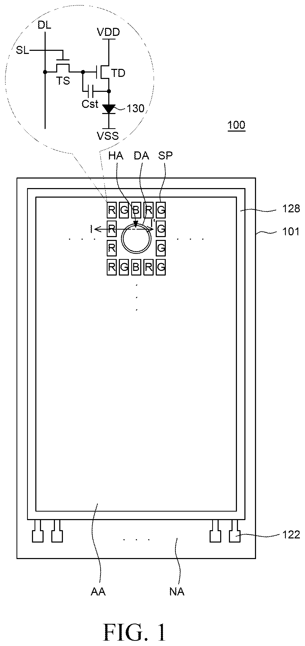
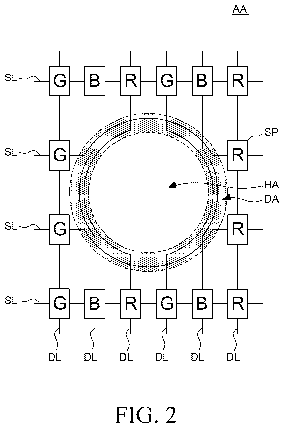
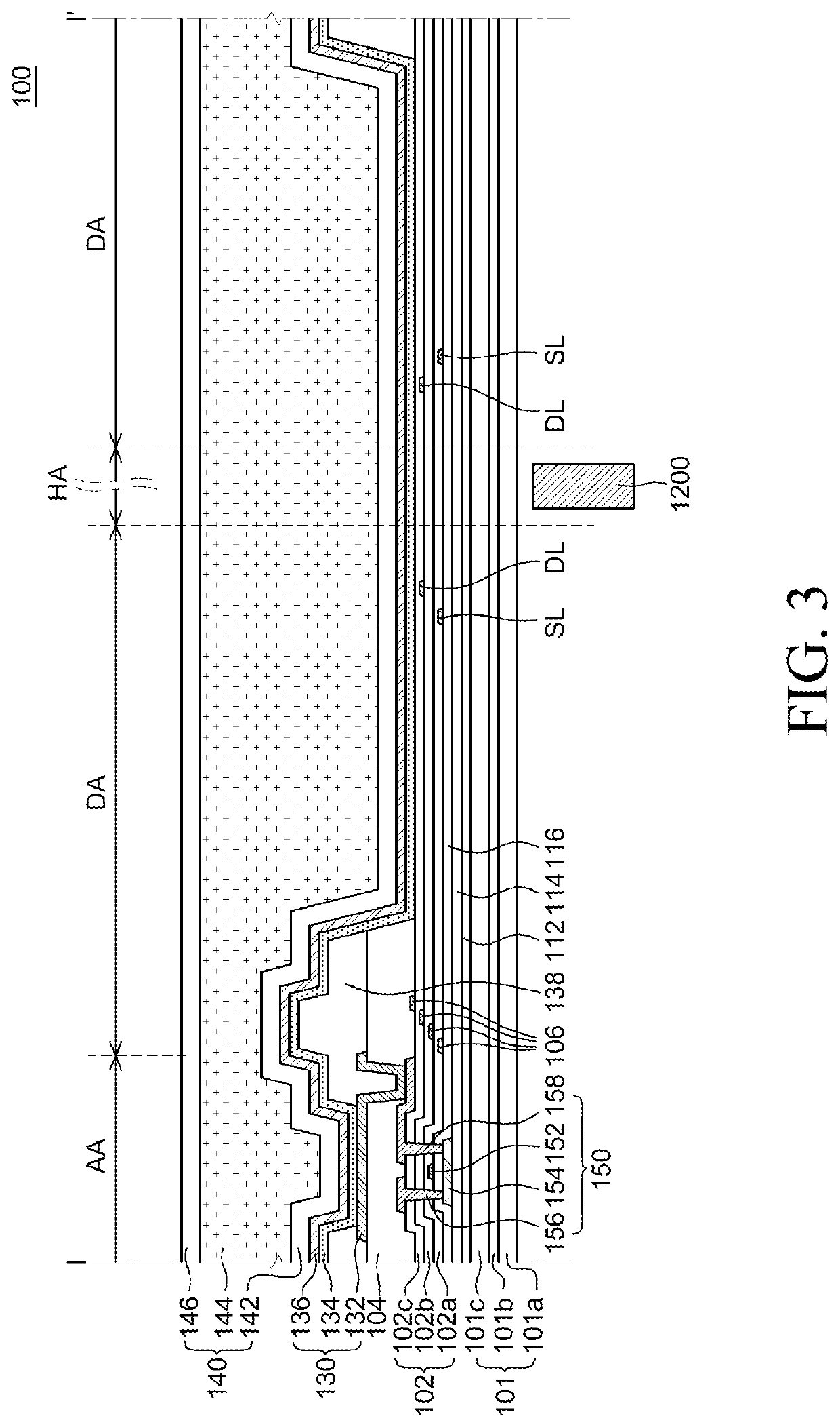
A display device according to an embodiment of the present disclosure includes a see-through area for camera in which a camera module is disposed, a routing area disposed around the see-through area for camera and overlapped by at least one data line and scan line, and a pixel area which includes the see-through area for camera and the routing area and includes a plurality of sub-pixels including an organic light emitting element and a cathode is disposed therein.

Description

CROSS-REFERENCE TO RELATED APPLICATIONS[0001]This application claims the priority of Korean Patent Application No. 10-2019-0171978 filed on Dec. 20, 2019, in the Korean Intellectual Property Office, the disclosure of which is incorporated herein by reference.BACKGROUNDTechnical Field[0002]The present disclosure relates to a display device, and more particularly, to a display device including a see-through area for camera within a pixel area.Description of the Related Art[0003]Image display devices, which display a variety of information on a screen, are a core technology of information and communication era and are becoming increasingly thinner, lighter, more portable, and higher in performance. Thus, display devices capable of eliminating disadvantages of heavy and bulky structures of cathode ray tubes (CRTs) have received attention.[0004]Examples of the display devices may include a liquid crystal display (LCD) device, a plasma display panel (PDP), an electroluminescence display (...

Claims


Application Information

Patent Timeline
IPC IPC(8): H01L27/32H01L51/52G06F3/041
CPCH01L27/3234H01L27/323G06F3/0412H01L51/5253H01L27/3246H01L27/3276G06F3/0445H10K59/65H10K59/40H10K59/8731G06F3/0446G06F2203/04112G06F2203/04111H10K59/122H10K59/131Y02E10/549G06F3/041H04N23/57H01L33/12H01L27/14678H10K50/844H10K50/816H10K50/828H10K59/35H10K59/123H10K59/353H10K59/1213H10K59/1216H10K2102/00G09G2300/0408G09G2300/0804H10K2102/311H10K77/111G09G2380/02G02F1/133305G06F1/1652G09F9/301
Inventor HAN, JONGHYUNYOON, SUNGWOOKSONG, MINSEOB
Owner LG DISPLAY CO LTD
Learn More