Redundant robotic arm control method, redundant robotic arm controller, and computer readable storage medium

a robotic arm and controller technology, applied in the field of automatic control technology, can solve problems such as parameter perturbation, external interference, unmodeled dynamics, etc., and achieve the effect of reducing the uncertainty of the robotic arm model, reducing the risk of external forces to act on the robotic arm, and reducing the risk of external forces

Active Publication Date: 2021-07-01
UBTECH ROBOTICS CORP LTD
View PDF3 Cites 2 Cited by
  • Summary
  • Abstract
  • Description
  • Claims
  • Application Information

AI Technical Summary

Problems solved by technology

Since the robotic arm is a complex system, it has uncertainties such as parameter perturbation, external interference, and un-modeled dynamics.
Therefore, the modeling model of the robotic arm also has uncertainty.
For the robotic arm, it may encounter obstacles d

Method used


Image

  • Redundant robotic arm control method, redundant robotic arm controller, and computer readable storage medium
  • Redundant robotic arm control method, redundant robotic arm controller, and computer readable storage medium
  • Redundant robotic arm control method, redundant robotic arm controller, and computer readable storage medium

Examples


first embodiment

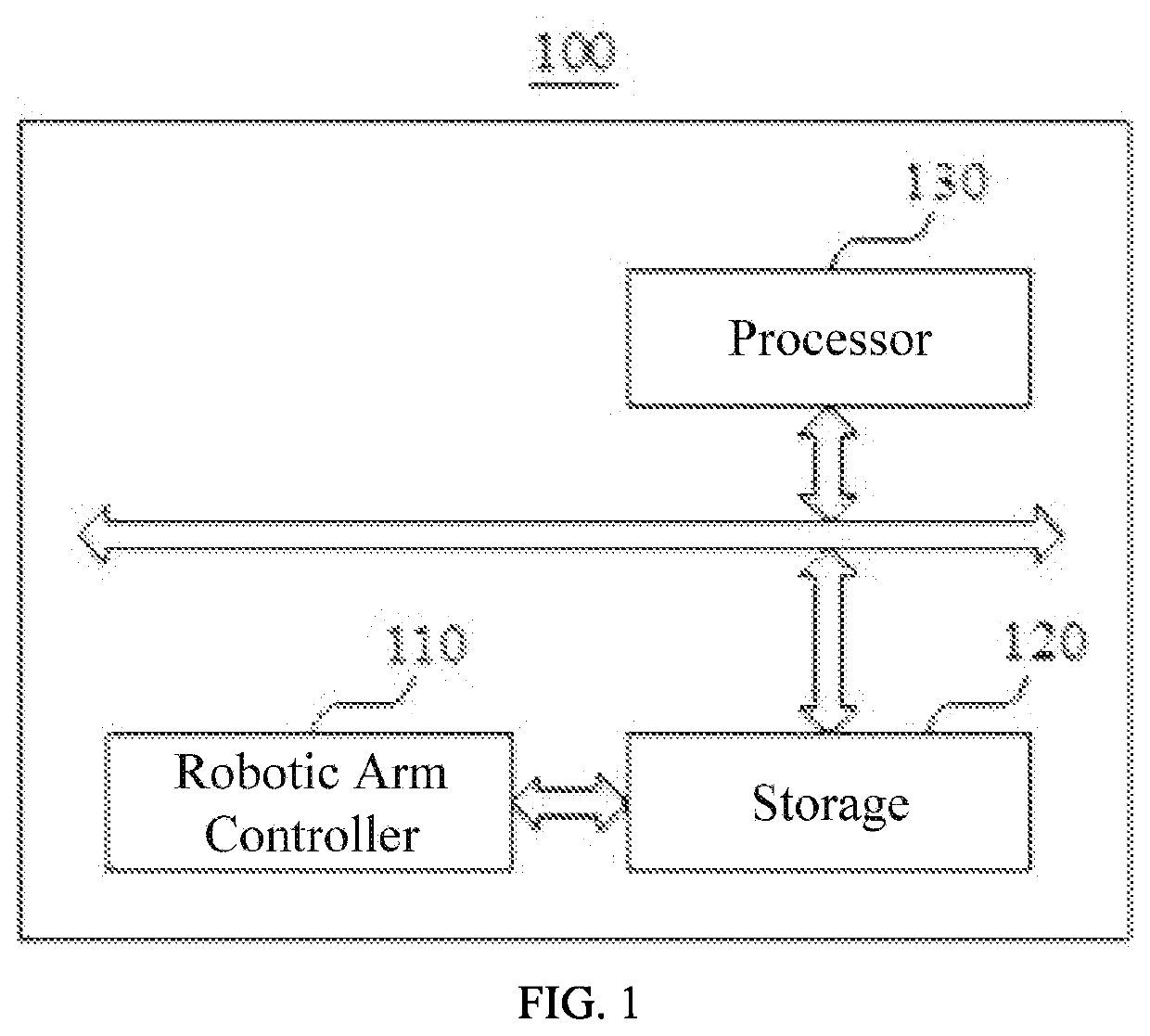
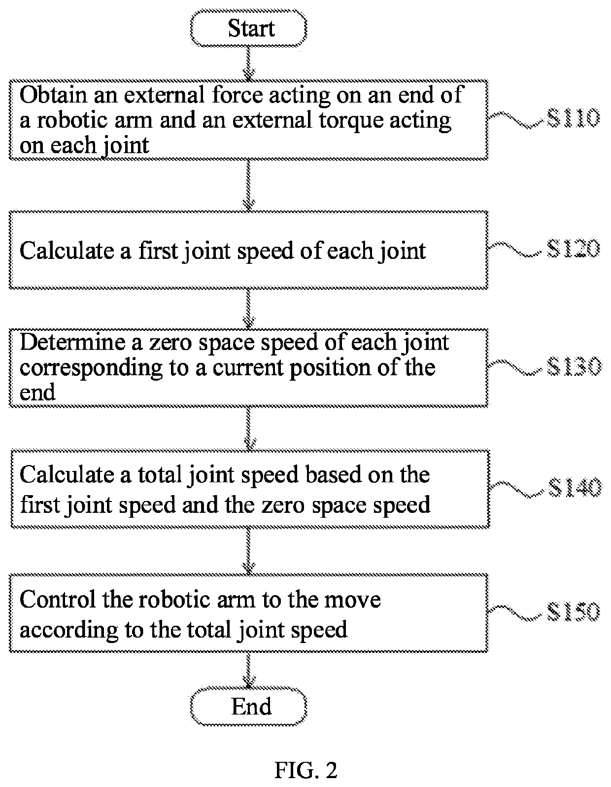
[0026]FIG. 2 is a flow chart of a redundant robotic arm control method according to the present disclosure. In this embodiment, a control method for a controller electrically connected to a redundant robotic arm or for the redundant robotic arm itself is provided. The method is a computer-implemented method executable for a processor. In one embodiment, the method may be implemented through the redundant robotic arm of FIG. 1 or a redundant robotic arm controller shown in FIG. 5. As shown in FIG. 2, the method includes the following steps.

[0027]S110: obtaining an external force acting on an end of the robotic arm and an external torque acting on each joint.

[0028]S120: calculating a first joint speed of each joint.

[0029]In this embodiment, the first joint speed of each joint is calculated based on a degree of influence (e.g., position, speed, or other motion influence) of the joint on the end in each motion dimension and the external force acting on the end, where the first joint spe...

second embodiment

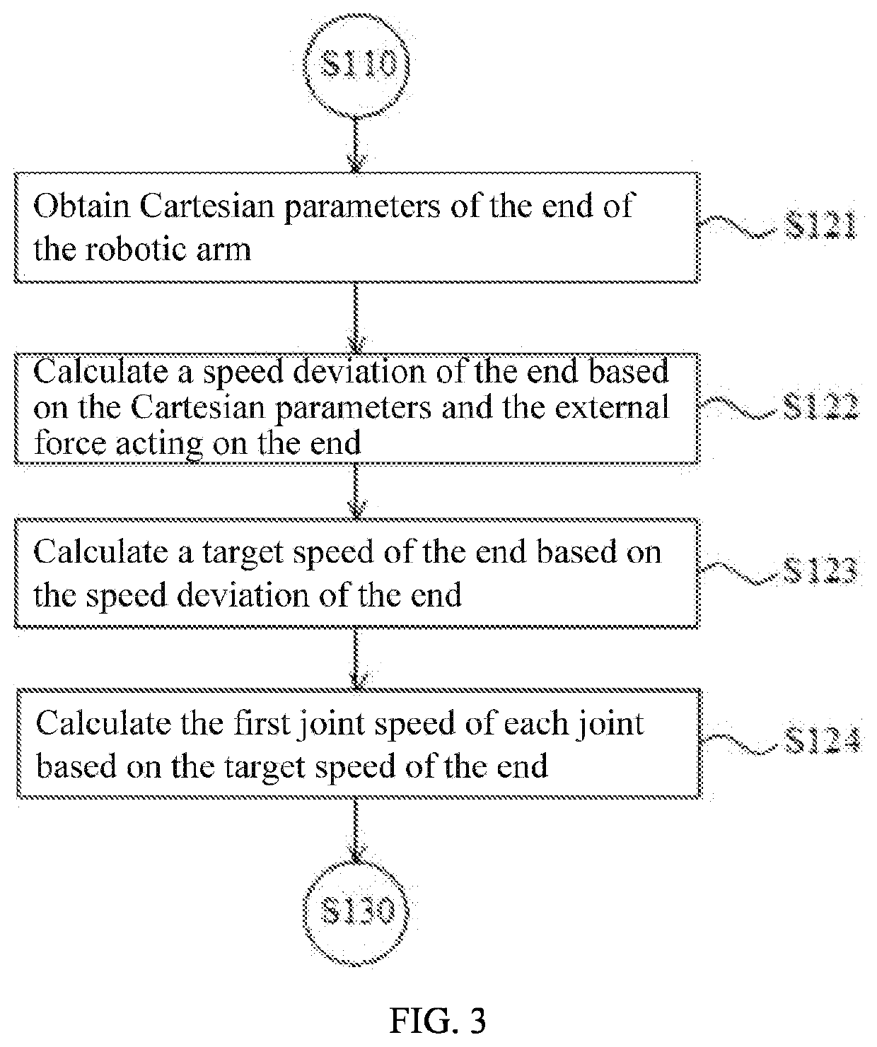
[0035]FIG. 3 is a flow chart of a redundant robotic arm control method based on the redundant robotic arm control method of FIG. 2. As shown in FIG. 3, in this embodiment, the above-mentioned step of calculating the first joint speed of each joint based on the degree of influence of the joint on the end in each motion dimension and the external force acting on the end may include sub-steps S121-S124.

[0036]S121: obtaining Cartesian parameters of the end of the robotic arm, where the Cartesian parameters include an inertia parameter, a damping parameter, and a stiffness parameter of each dimension of the end.

[0037]In which, the larger the inertia parameter, the higher the stability of the robotic arm when subjected to external forces, the larger the damping parameter, the faster the energy dissipation of the robotic arm during collision, and the larger the stiffness parameter, the higher the accuracy of the position of the end. Therefore, the Cartesian parameters at the end of the rob...

third embodiment

[0051]FIG. 4 is a flow chart of a redundant robotic arm control method based on the redundant robotic arm control method of FIG. 2. As shown in FIG. 4, in this embodiment, the above-mentioned step of determining the zero space speed of each joint corresponding to the current position of the end based on the link torque of the external force acting on the link with respect to the joint may include sub-steps S131-S135.

[0052]S131: calculating a first torque acting on each joint that is generated by the external force acting on the link.

[0053]S132: calculating a speed deviation of each joint based on the first torque of the joint, where the speed deviation is a difference between an actual speed of the joint and an expected speed of the joint.

[0054]S133: calculating a speed control weight of each joint based on a weight coefficient of the joint and the speed deviation of the joint.

[0055]S134: calculating a zero space basis vector of the robotic arm.

[0056]In this embodiment, the zero spa...


PUM


Abstract

The present disclosure provides a redundant robotic arm control method, a redundant robotic arm, and a computer readable storage medium. The method includes: obtaining an external force acting on an end of the robotic arm and an external torque acting on each joint; calculating a first joint speed of each joint based on a degree of influence of the joint on the end in each motion dimension and the external force acting on the end; determining a zero space speed of each joint corresponding to a current position of the end based on a link torque of an external force acting on a link with respect to the joint; calculating a total joint speed based on the first joint speed and the zero space speed; and controlling the robotic arm to the move according to the total joint speed.

Description

CROSS REFERENCE TO RELATED APPLICATIONS[0001]The present disclosure claims priority to Chinese Patent Application No. 201911403020.2, filed Dec. 30, 2019, which is hereby incorporated by reference herein as if set forth in its entirety.BACKGROUND1. Technical Field[0002]The present disclosure relates to automatic control technology, and particularly to a redundant robotic arm control method, a redundant robotic arm controller, and computer readable storage medium.2. Description of Related Art[0003]Robotic arm is to a complex system with high precision, multiple inputs and outputs, high nonlinearity, and strong coupling. Because of its unique operational flexibility, it has been widely used in industrial assembly, industrial safety, explosion-proof, and the like. Since the robotic arm is a complex system, it has uncertainties such as parameter perturbation, external interference, and un-modeled dynamics. Therefore, the modeling model of the robotic arm also has uncertainty. For differ...

Claims


Application Information

Patent Timeline
IPC IPC(8): B25J9/16B25J9/02B25J13/08
CPCB25J9/1607B25J9/023B25J9/1643B25J9/1651B25J13/085B25J9/1633B25J9/1612B25J9/1664G05B2219/40367G05B2219/39529G05B2219/40599B25J9/1666B25J9/1676
Inventor HUANG, LIQUNREN, XIAOYUWANG, YUESONGXIONG, YOUJUN
Owner UBTECH ROBOTICS CORP LTD
Why Eureka
Try Eureka