
Coal mine conveying vehicle

A technology for conveying vehicles and coal mines, which is applied in the direction of mining vehicles, transport buses, transportation and packaging, etc. It can solve the problems of difficult control of movement speed and achieve the effects of reducing resistance, reducing wear and reducing friction

Inactive Publication Date: 2021-07-16
姚冬
View PDF0 Cites 1 Cited by
  • Summary
  • Abstract
  • Description
  • Claims
  • Application Information

AI Technical Summary

Problems solved by technology

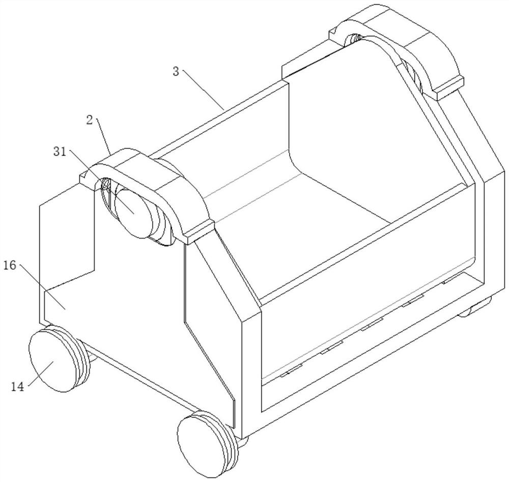
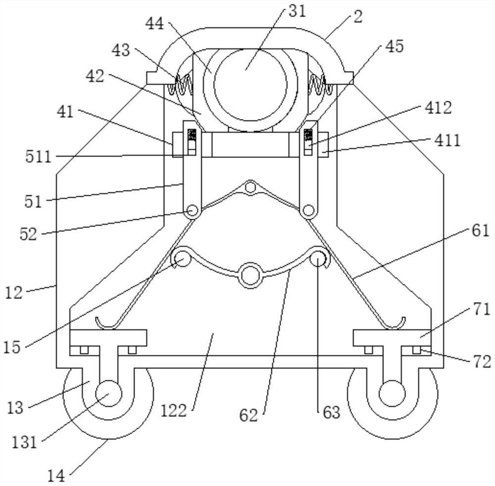
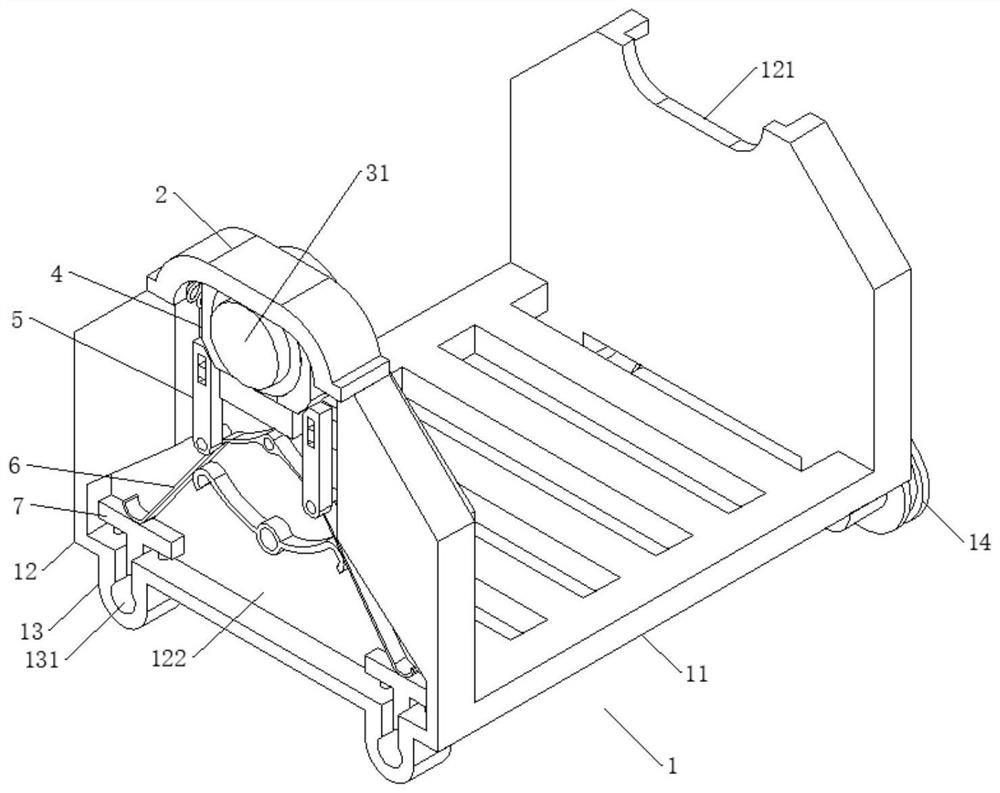
[0003] The object of the present invention is to provide a coal mine transport vehicle, through which the hopper equipped with coal mines is always kept vertical under the action of gravity, and slides to the lower end along the half-waist hole provided on the vertical plate, thereby pushing the upper side of the cross bar The corresponding sliding rod slides down to realize the rotation of the V-shaped rod, and push the friction block to stick to the rotating shaft of the roller to achieve the effect of deceleration and braking, which solves the problem that the existing coal mine transport vehicle is difficult to control the speed of the slope

Method used


Image

  • Coal mine conveying vehicle
  • Coal mine conveying vehicle
  • Coal mine conveying vehicle

Examples


Embodiment Construction

[0025] The following will clearly and completely describe the technical solutions in the embodiments of the present invention with reference to the accompanying drawings in the embodiments of the present invention. Obviously, the described embodiments are only some, not all, embodiments of the present invention. Based on the embodiments of the present invention, all other embodiments obtained by persons of ordinary skill in the art without creative efforts fall within the protection scope of the present invention.

[0026] In describing the present invention, it is to be understood that the terms "opening", "upper", "lower", "thickness", "top", "middle", "length", "inner", "surrounding" etc. Indicating orientation or positional relationship is only for the convenience of describing the present invention and simplifying the description, and does not indicate or imply that the components or elements referred to must have a specific orientation, be constructed and operated in a sp...


PUM


Abstract

The invention discloses a coal mine conveying vehicle, and relates to the technical field of coal mine electromechanical equipment. The vehicle comprises a frame, the frame comprises a bottom plate and vertical plates, the vertical plates are arranged at the two opposite side edges of the bottom plate, half-kidney-shaped holes are formed in the tops of the vertical plates, two mounting bases are symmetrically arranged on the bottom faces of the vertical plates, sliding grooves are formed in the mounting bases, and cavities communicating with the half-kidney-shaped holes and the sliding grooves are formed in one side faces of the vertical plates; a hopper is rotationally installed between the two vertical plates, and a shaft body of the hopper is installed in the clamping part in a matched mode and is fixed through a fixing part fixedly installed at the top end of the half-kidney-shaped hole. Rollers are rotationally mounted at the bottoms of the sliding grooves, friction parts making contact with roller shaft bodies are further mounted in the sliding grooves, and the tops of the friction parts make contact with the elastic pieces. The hopper filled with a coal mine pushes the corresponding sliding rods on the transverse rod to slide downwards under the action of gravity, the first V-shaped rod is pushed to rotate, the friction blocks are pushed to be tightly attached to the rotating shafts of the rolling wheels, and the speed reducing and braking effects are achieved.

Description

technical field [0001] The invention belongs to the technical field of coal mine electromechanical equipment, in particular to a coal mine transport vehicle. Background technique [0002] The transport vehicle composed of the frame and the hopper is installed on the track, which is convenient for transporting the coal mine at the top of the slope to the bottom of the slope. During the working process of the existing transport vehicle, due to the heavy weight of the vehicle loaded with coal mine, it is difficult to move along the track. During the sliding process, the speed gradually increases under the acceleration of gravity. The deceleration device composed of the front equipment and the buffer device receives a large impact and is easy to damage the deceleration device. Contents of the invention [0003] The object of the present invention is to provide a coal mine transport vehicle, through which the hopper equipped with coal mines is always kept vertical under the act...

Claims


Application Information

Patent Timeline
Patent Type & Authority Applications(China)
IPC IPC(8): B61D11/00B61D11/02B61H11/04
CPCB61D11/00B61D11/02B61H11/04
Inventor 姚冬
Owner 姚冬
Learn More