Utility vehicle having continuously variable transmission

a technology of transmission and utility vehicle, which is applied in the direction of vehicle sub-unit features, transportation and packaging, and jet propulsion mounting, etc., can solve the problems of increasing the complexity of the vehicle body panel arrangement and increasing the manufacture cost, and achieves the effects of increasing the manufacture cost of the exterior side panel, increasing the capacity, and being convenient to manufactur

Active Publication Date: 2021-07-08
KUBOTA LTD
View PDF0 Cites 1 Cited by
  • Summary
  • Abstract
  • Description
  • Claims
  • Application Information

AI Technical Summary

Benefits of technology

[0016]In the above-described configuration, the exterior side panel which creates a space for a passenger or a rider comprises a double-layered structure consisting of an inner wall and an outer wall. Further, between these inner and outer walls, there is formed an intake chamber for the intake system for cooling the CVT. Such intake chamber can be readily made by the blow molding technique, not inviting increase in the manufacture cost of the exterior side panel. Moreover, such intake chamber can be formed with a sufficiently large capacity. As the intake chamber serving as a temporary storage chamber for ambient air is incorporated in a passage for introducing ambient air into the CVT case accommodating the CVT, feeding of the ambient air to the CVT case can proceed smoothly. Further, if a condition of the position of the intake opening portion and the connecting position of the intake hose facing the intake chamber is met, then, it becomes possible to carry out the air feeding at any portion of the lateral wall of the exterior side panel, so that designing flexibility will be increased advantageously.
[0017]The intake opening portion may be provided on either side of the lateral wall of the exterior side panel. But, if this intake opening

Problems solved by technology

This results in increased complexity of the vehicle body pane

Method used


Image

  • Utility vehicle having continuously variable transmission
  • Utility vehicle having continuously variable transmission
  • Utility vehicle having continuously variable transmission

Examples


Embodiment Construction

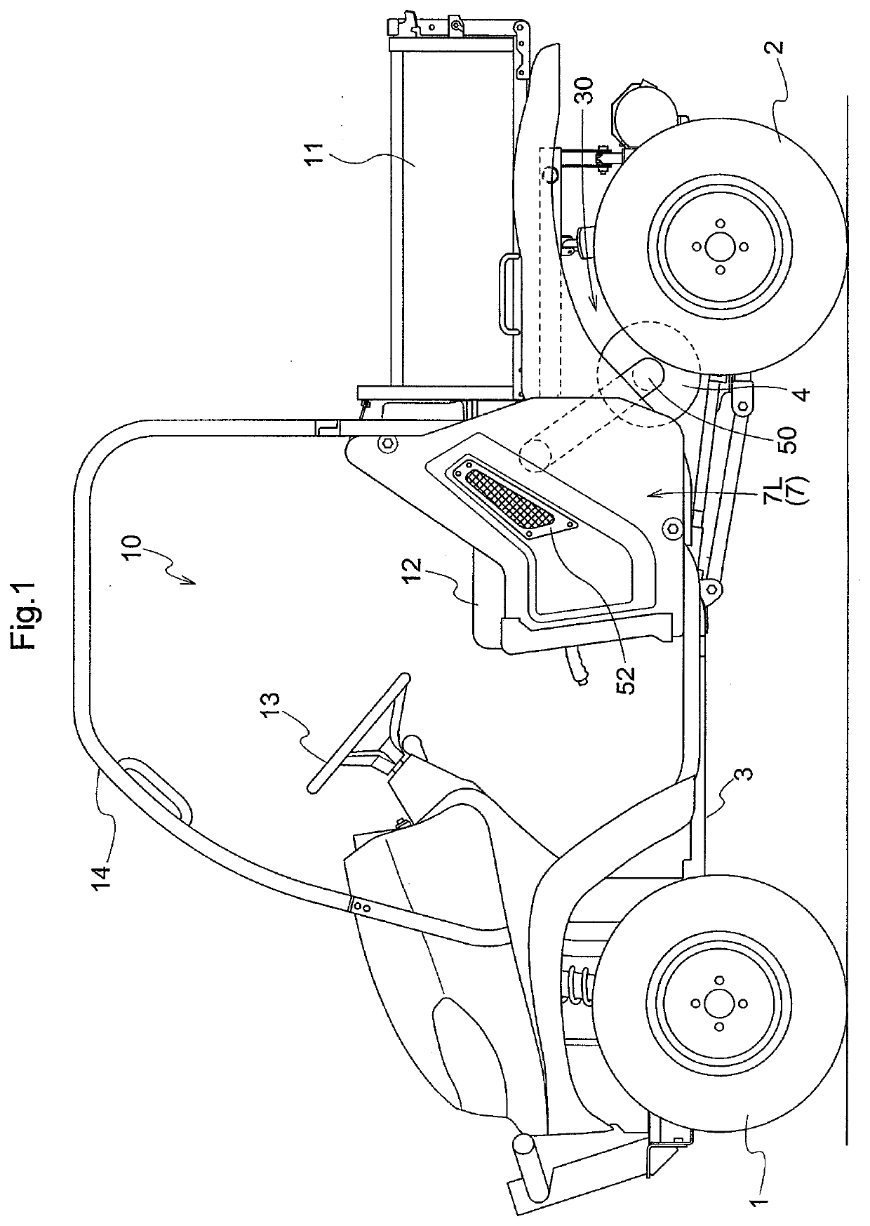
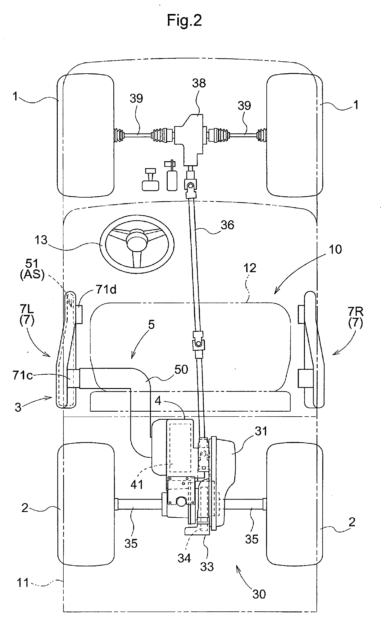
[0025]As shown in FIG. 1 and FIG. 2, a utility vehicle includes a vehicle body frame 3 which is supported on the ground surface via a pair of left and right front wheels 1 which can be freely operated for steering and a pair of left and right rear wheels 2. At the center portion of this vehicle body frame 3, a driving section 10 is disposed. At a rear portion of the vehicle body frame3, a cargo bed is provided. Rearwardly of the driving section 10 and downwardly of the cargo bed 11, a power source unit 30 is disposed.

[0026]This utility vehicle is configured as a four-wheel drive type in which driving power from the power source unit 30 is transmitted to the front wheels 1 and the rear wheels 2, the utility vehicle being configured d for use in multiple-purposes of utility works, such as farming works, a transporting work, etc. A ROPS frame 14 for protecting the driving section 10 is provided to surround this driving section 10. The cargo bed 11 is configured as a dumping type that a...


PUM


Abstract

A utility vehicle has a CVT, an engine providing power to the CVT, a CVT case accommodating the CVT, front and rear wheels supporting the vehicle body frame on the ground surface and an exterior side panel supported to the vehicle body frame. The exterior side panel includes an inner wall located inside a vehicle cabin and an outer wall located outside the vehicle cabin. An intake chamber is formed between the inner wall and the outer wall of the exterior side panel. An intake opening portion is provided in the exterior side panel for introducing ambient air present around the exterior side panel to the intake chamber. The intake chamber and the CVT case are connected and communicated to each other via an intake hose.

Description

TECHNICAL FIELD[0001]This invention relates to a utility vehicle having a CVT, more particularly to a cooling system for its CVT.BACKGROUND ART[0002]U.S. Pat. No. 9,217,501 discloses a cooling system for a continuously variable transmission (to be referred to as “CVT” in short, hereinafter). In this cooling system, an intake system and an exhaust system are connected to a CVT case accommodating a CVT. The intake system consists of an air inlet portion, a conduit and a duct. The duct is connected to the CVT case. The conduit connects the duct to the air inlet portion. The air inlet portion has an air inlet. An opening is formed in a vehicle body panel constituting a side wall of a cargo bed of the utility vehicle, and a filter is attached to this opening. The air inlet portion is incorporated within the vehicle body panel so as to allow introduction of air passing through the filter via the air inlet.[0003]U.S. Pat. No. 9,725,023 too discloses a cooling system for a CVT mounted on a ...

Claims


Application Information

Patent Timeline
IPC IPC(8): F16H57/04F16H57/027B60K17/06
CPCF16H57/0416F16H2057/02056B60K17/06F16H57/027F16H57/035F16H57/0404F16H57/0489B60Y2400/72B60Y2200/20B60Y2200/124B60K11/06B60K11/08B60K2005/003
Inventor ALLICOCK, NICHOLAS
Owner KUBOTA LTD
Why Eureka
Try Eureka