Substrate processing apparatus

Pending Publication Date: 2021-07-08
DAINIPPON SCREEN MTG CO LTD
View PDF0 Cites 0 Cited by
  • Summary
  • Abstract
  • Description
  • Claims
  • Application Information

AI Technical Summary

Benefits of technology

The present invention is for a device used to process substrates. It aims to reduce the pressure loss in the exhaust pipe and reduce the size of the device. It achieves these goals by making modifications to the exhaust system. These modifications result in a more efficient exhaust pipe that reduces pressure and a smaller space requirement for the device.

Problems solved by technology

In a case where the exhaust switching apparatus is disposed in the subfab, like in the case described in Document 1, since the length of an exhaust pipe connecting from a processing part of the substrate processing apparatus to the exhaust switching apparatus becomes longer, a pressure loss in the exhaust pipe disadvantageously increases.
Though there is a possible case where the exhaust switching apparatus is disposed at the side of the processing part, to thereby reduce the length of the exhaust pipe, the footprint of the substrate processing apparatus on the whole disadvantageously increases.

Method used


Image

  • Substrate processing apparatus
  • Substrate processing apparatus
  • Substrate processing apparatus

Examples


Embodiment Construction

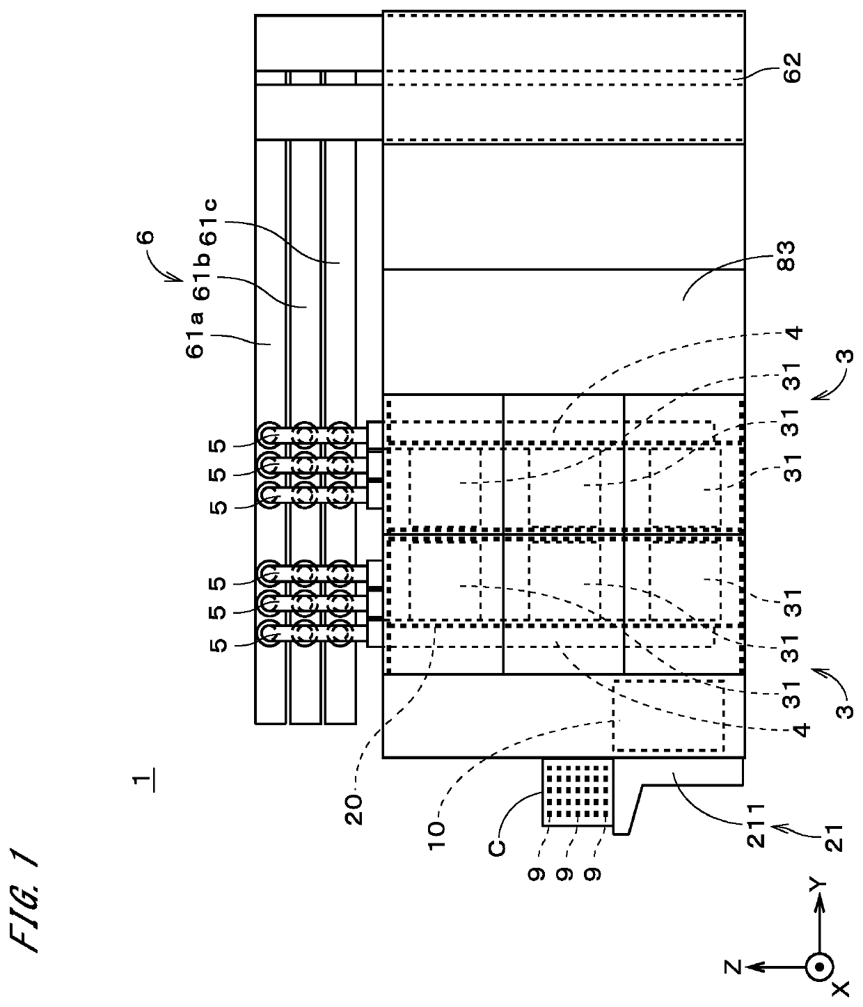
[0026]FIG. 1 is a view showing an appearance of a substrate processing apparatus 1 in accordance with one preferred embodiment of the present invention. The substrate processing apparatus 1 is a single-substrate processing apparatus for processing substrates 9 one by one by a processing part 31 described later. In FIG. 1, three directions orthogonal to one another are shown as an X direction, a Y direction, and a Z direction. Typically, the Z direction is an up-and-down direction (vertical direction) and the X direction and the Y direction are horizontal directions.

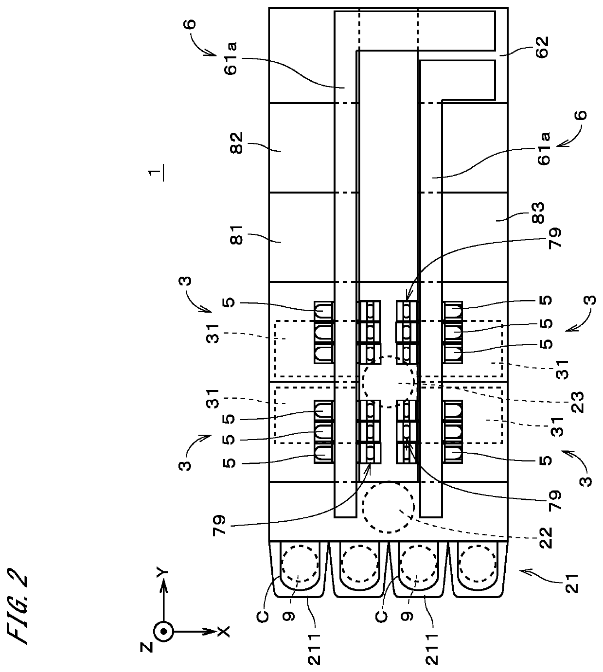
[0027]FIG. 2 is a plan view showing the substrate processing apparatus 1 as viewed from the (+Z) side toward the (−Z) direction. As shown in FIGS. 1 and 2, the substrate processing apparatus 1 includes a control part 10, a support frame 20, a container mounting part 21, an indexer robot 22, a center robot 23, a plurality of multilayer units 3, and a plurality of collecting pipe groups 6. The control part 10 performs a gen...


PUM

PropertyMeasurementUnit
Pressureaaaaaaaaaa
Flow rateaaaaaaaaaa
Areaaaaaaaaaaa

Abstract

In a substrate processing apparatus (1), above a plurality of processing parts (31) arrayed in an up-and-down direction, arranged are a plurality of collecting pipes (61a to 61c). The plurality of collecting pipes (61a to 61c) correspond to a plurality of fluid classifications, respectively. Further, provided are a plurality of exhaust pipes (4) extending upward from the plurality of processing parts (31), into which exhaust gases from the processing parts (31) flow, respectively. At an upper end portion of each of the exhaust pipes (4), provided is a flow path switching part (5) which connects the upper end portion to the plurality of collecting pipes (61a to 61c) and switches a flow path of the exhaust gas flowing in the exhaust pipe (4) among the plurality of collecting pipes (61a to 61c). In the substrate processing apparatus (1), it is possible to reduce a pressure loss in the exhaust pipe (4) and reduce a footprint.

Description

TECHNICAL FIELD[0001]The present invention relates to a substrate processing apparatus.BACKGROUND ART[0002]In a process of manufacturing a semiconductor device, conventionally, a substrate processing apparatus has been used, which performs processings on a semiconductor substrate (hereinafter, referred to simply as a “substrate”) by using various types of processing fluids. Further, Japanese Patent Application Laid-Open No. 2016-72480 (Document 1) discloses an exhaust switching apparatus for switching an outlet destination of exhaust gas discharged from a substrate processing apparatus in accordance with the kind of processing fluid, among three exhaust apparatuses. In Document 1, the substrate processing apparatus is provided in a clean room, and the exhaust switching apparatus is provided in a downstairs space of the clean room, which is termed a subfab. By providing the exhaust switching apparatus, it becomes possible to reduce environmental load. Furthermore, WO 2014 / 103523 disc...

Claims


Application Information

Patent Timeline
IPC IPC(8): H01L21/67B08B15/02B01D46/00
CPCH01L21/67051B01D46/0041B08B15/02H01L21/6719H01L21/304H01L21/67017H01L21/67253H01L21/67173H01L21/67178
Inventor NISHIDE, HAJIMEKANG, KWICHANGMATSUMOTO, TAKAO
Owner DAINIPPON SCREEN MTG CO LTD
Why Eureka
Try Eureka