
Inter-connecting locking mechanism and grip channel

a technology of interconnection and locking mechanism, which is applied in the direction of fastening means, electrical equipment, pipe elements, etc., can solve the problems of arcing and chafing, indirect damage, and chafing of wire bundles, so as to improve the securing functionality of the device

Active Publication Date: 2021-07-15
RENESSELAER POLYTECHNIC INST
View PDF0 Cites 0 Cited by
  • Summary
  • Abstract
  • Description
  • Claims
  • Application Information

AI Technical Summary

Benefits of technology

The solution significantly reduces the risk of Repetitive Strain Injuries, minimizes Foreign Object Damage, and enhances safety by reducing muscle fatigue and the risk of electrical shorts, while also cutting maintenance costs and improving installation efficiency.

Problems solved by technology

Hydraulic fluid and other external factors are very damaging to connector grommets and wire bundle clamps, leading to indirect damage, such as arcing and chafing.
Through the continual motion of the aircraft and the use of chemicals, such as hydraulic fluid, oils, or washing detergents, the wire bundles may chafe and the rubber sleeve may erode and expose the wires to the sharp metal edge of the clamp.
Wiring exposed to high heat can accelerate degradation, insulation dryness, and cracking.
Direct contact with a high heat source can quickly damage insulation.
Even low levels of heat can degrade aircraft wiring over long periods of time.
Clamps not installed properly can further accelerate the wiring degradation process.
Improper routing, clamping, and terminating during initial installation or during a modification can lead to damage.
These clamps use hardware and are difficult to install around one or more longitudinal elements, like bundles of wires, tubing, or other similar materials.
However, these clamps are difficult to replace and they have led to severe strain injuries of the hands, such as carpal tunnel syndrome.
There are inherent problems with the material and the design of this original clamp, the material is conductive and can lead to arcing, and the design requires the technicians to pull it apart causing injuries to the hands.
Additionally, the need for a bolt / screw, washer, and nut to attach the clamp to the aircraft opens up for the possibility of Foreign Object Damage (FOD).

Method used


Image

  • Inter-connecting locking mechanism and grip channel
  • Inter-connecting locking mechanism and grip channel
  • Inter-connecting locking mechanism and grip channel

Examples


Embodiment Construction

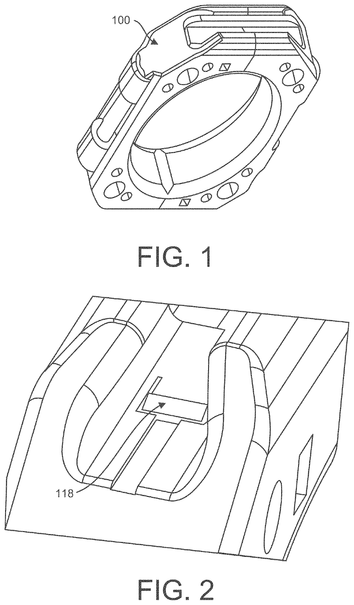
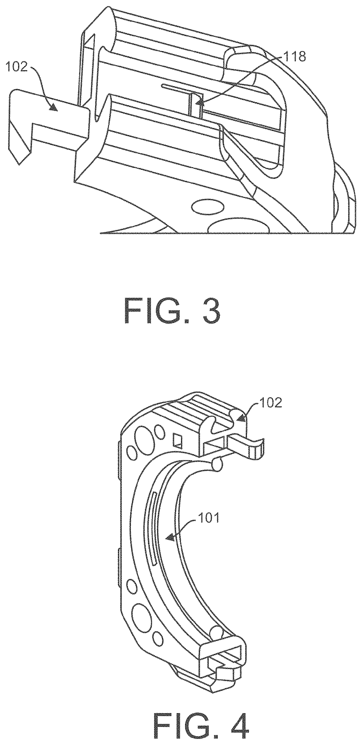
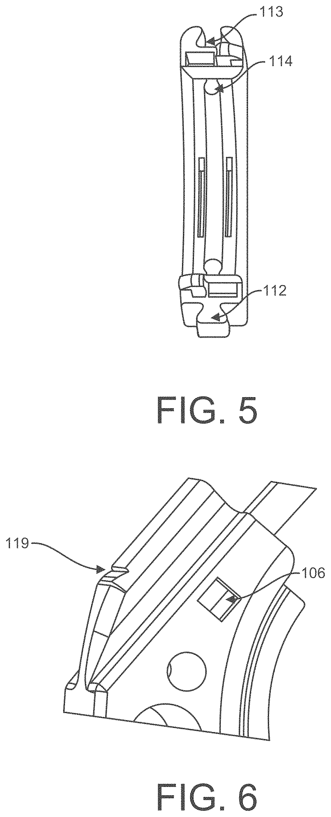
[0011]The device is designed as two halves made of thermoplastics and comprised of one or more complementary snap-fit tabs that interlock together and rest flush against one another in a manner that lines up one half with its respective complementary snap-fit tab or tabs with the hole of the second half with secondary complementary snap-fit tab or tabs, FIGS. 3,4,5, 15, 20, and 24. The securing device may include a grip to improve the securing functionality of the device, FIGS. 7, 8, 15, and 16.

[0012]The device is therefore an object of the exemplary embodiments disclosed herein to alleviate the disadvantages in the art and provide an interconnecting clamp that is molded from a combination of thermoplastics and rubber components in order to provide a lightweight but sturdy circumferential clamping device. The disassembly tool, FIGS. 11 and 23, fits easily into a hand fingers to reach areas and allows the technician to depress the snap-fits of the smart clamp with one hand and withou...


PUM


Abstract

A device for securing aircraft wiring includes a first body having a first end, a second end opposite the first end, and a concave portion extending semi-annularly between the first end and the second end, the concave portion having a surface defining a wire-receiving space. In an embodiment, the device includes a grip connection element configured to slidably mate with a gripping element. In an embodiment, the device includes a first hole extending into the second end, a first recess extending from the first hole, and a first tab including a first portion and a first latch, the first portion of the first tab projecting in a first direction from the first end of the first body, the first latch of the first tab projecting in a second direction from the first portion of the first tab, the first hole configured to receive a tab identical to the first tab.

Description

CROSS REFERENCE TO RELATED APPLICATIONS[0001]This application is a continuation of co-pending application Ser. No. 16 / 004,855, filed Jun. 11, 2018, entitled “Inter-Connecting Locking Mechanism and Grip Channel”, which claims the benefit of provisional application No. 62 / 519,459, filed Jun. 14, 2017.FIELD OF INVENTION[0002]The technology relates to a method and apparatus comprised of an interconnecting clamp in an aircraft for securing wiring harnesses. Furthermore, the device pertains to the general field of aviation manufacturing fastening devices, especially a clamp, and has certain specific application to aircraft electrical wiring. More particularly, the present technology relates to attaching wirings and other mechanical components such as tubing, piping or other equipment requiring a substantially circular clamp. Additionally, the device makes use of a novelty ergonomic hand tool for the disassembly of the embodiment herein.BACKGROUND OF THE INVENTION[0003]Wire bundles that ma...

Claims


Application Information

Patent Timeline
Patent Type & Authority Applications(United States)
IPC IPC(8): F16L3/10
CPCF16L3/1091F16L55/035F16L3/222H02G3/32F16B21/086
Inventor RHYSING, DARYIAN
Owner RENESSELAER POLYTECHNIC INST
Learn More