Chained Iterative Application of Computer Aided Generative Design for Optimized Geometries

a geometries and computer aided generative technology, applied in the field of chained iterative application of computer aided generative design for optimizing geometries, can solve the problems of severe affecting the performance of traditional brep systems, and achieve the effects of reducing manufacturing costs, reducing manufacturing time, and reducing manufacturing costs

Pending Publication Date: 2021-07-15
PARAMETRIC TECH CORP
View PDF0 Cites 2 Cited by
  • Summary
  • Abstract
  • Description
  • Claims
  • Application Information

AI Technical Summary

Benefits of technology

[0008]The system can enable a designer to iteratively refine optimized topologies of objects using generative design methodologies. In contrast to conventional systems discussed above, the system enables a designer to reuse previously generated optimized geometries to generate revised optimized geometries that correspond to updated design requirements. For example, a designer can generate an initial optimized geometry for a body object using an initial set of design/optimization criteria, including, for example, design parameters and a design recipe discussed below. The designer can then update a direction of force applied to a body object area. In response to the update, the system can generate an updated optimized geometry for the body object corresponding to the updated optimization criteria, such as the changed force direction, that is deri

Problems solved by technology

The system is useful for a modeling task where the number of surfaces or surface-to-surface calcu

Method used


Image

  • Chained Iterative Application of Computer Aided Generative Design for Optimized Geometries
  • Chained Iterative Application of Computer Aided Generative Design for Optimized Geometries
  • Chained Iterative Application of Computer Aided Generative Design for Optimized Geometries

Examples


Embodiment Construction

[0033]In the following description, references are made to various embodiments in accordance with which the disclosed subject matter can be practiced. Some embodiments may be described using the expressions one / an / another embodiment or the like, multiple instances of which do not necessarily refer to the same embodiment. Particular features, structures or characteristics associated with such instances can be combined in any suitable manner in various embodiments unless otherwise noted.

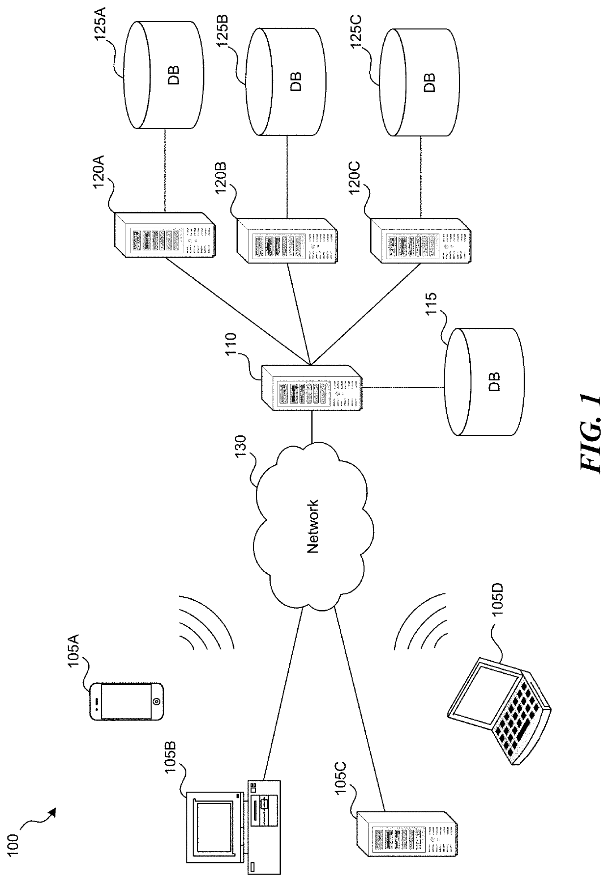
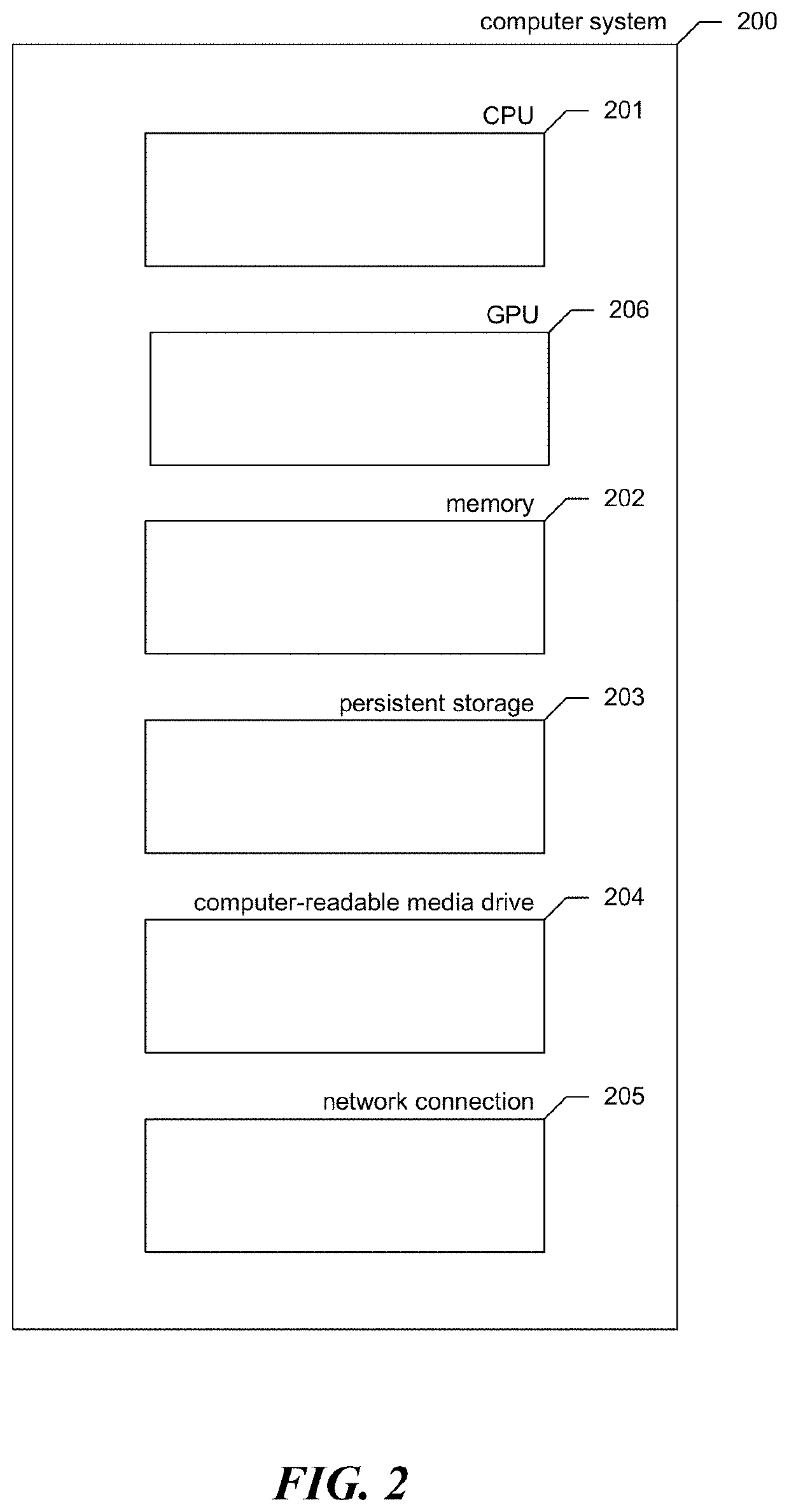
[0034]FIG. 1 is a system diagram illustrating an example of a computing environment 100 upon which a generative design system can be implemented. In some implementations, environment 100 includes one or more client computing devices 105A-D, such as the computer system 200 (FIG. 2). Client computing devices 105 can operate in a networked environment using logical connections through a network 130 to one or more other computers, such as a server computing device. One or more users can use client computin...


PUM


Abstract

Generative design uses artificial intelligence to automatically create optimal designs from a set of system design requirements. A generative design system receives user-supplied design requirements and generates an optimized geometry by chaining iterative applications of computer aided generative design. In one aspect, the system uses the output of a first generative design process as a requirement of or as part of the design requirements for a second generative process, with or without intervening user input. In another aspect, the system enables designers to incrementally or iteratively specify and edit design requirements such that each resulting geometry is derived from a previously or most recently generated optimized geometry and optionally updated design requirements. The system, by using or reusing outputs and/or data from previous design iterations can produce subsequent designs more efficiently and quickly.

Description

RELATED APPLICATIONS[0001]The subject matter of this application is related to U.S. Provisional Application No. 62 / 738,714, filed on Sep. 28, 2018, Patent Cooperation Treaty Application No. PCT / US19 / 53916, filed on Sep. 30, 2018, U.S. application Ser. No. 15 / 079,815 filed Mar. 24, 2016, now U.S. Pat. No. 10,042,817, and U.S. Provisional Application No. 62 / 145,350, filed Apr. 9, 2015, all of which applications are incorporated herein by reference in their entireties.BACKGROUND OF THE INVENTION[0002]In the current iterative boundary representation (BREP) computer-aided design (CAD) paradigm a designer specifies the shape of each part and then must verify its functionality, both individually and in the context of the assembly. If the functionality is not confirmed, the designer must iterate the shape and the process repeats itself. There is no way around the fact that this is a “guess and check” process, although good intuition on the part of the human designer means good “guesses” for...

Claims


Application Information

Patent Timeline
IPC IPC(8): G06F30/12G06F30/20
CPCG06F30/12G06F30/20G06F30/23
Inventor HILLER, JONATHANBLANKENSHIP, JESSE C.
Owner PARAMETRIC TECH CORP
Why Eureka
Try Eureka