Unlock instant, AI-driven research and patent intelligence for your innovation.

Rear vehicle-body structure of vehicle

a rear vehicle and body technology, applied in the direction of vehicle components, superstructures, understructures, etc., to achieve the effect of improving the front-end collision load transfer performance of the tunnel portion and improving the side collision performan

Active Publication Date: 2021-07-22
MAZDA MOTOR CORP
View PDF0 Cites 8 Cited by
  • Summary
  • Abstract
  • Description
  • Claims
  • Application Information

AI Technical Summary

Benefits of technology

This disclosure is about a vehicle's rear body structure that improves the suspension system and increases its stability, making it easier to steer.

Problems solved by technology

In this regard, Japanese Patent Laid-Open No. 2013-163470 does not disclose providing the structure disclosed therein with a reinforcement frame and the like to connect the rear end of the floor tunnel and a support portion (lower arm support portion) supporting a lower arm of the rear suspension.

Method used


Image

  • Rear vehicle-body structure of vehicle
  • Rear vehicle-body structure of vehicle
  • Rear vehicle-body structure of vehicle

Examples


Embodiment Construction

[0029]An embodiment of the present disclosure will be described with reference to the drawings.

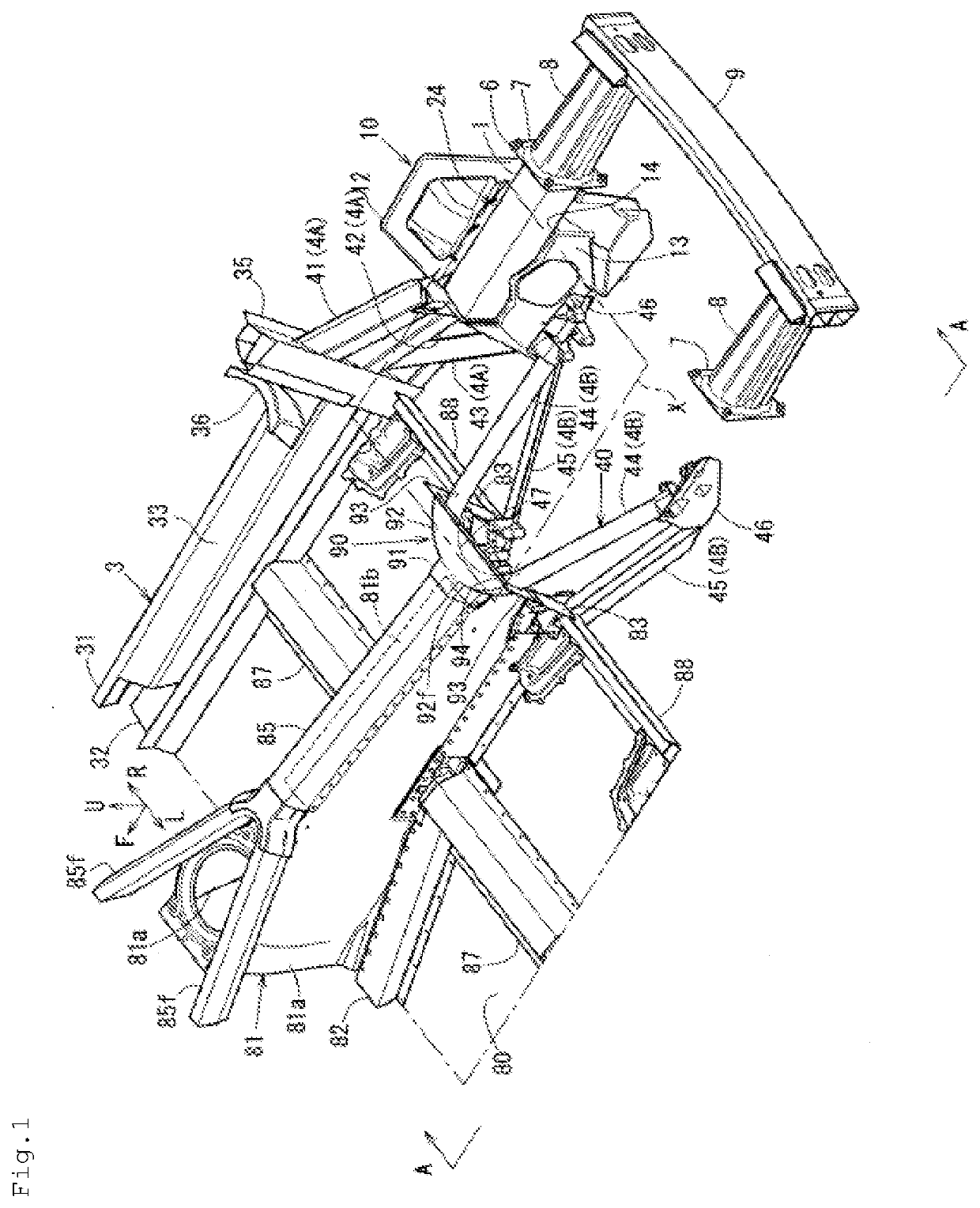
[0030]A vehicle in the present embodiment is a sports car that has a so-called space frame structure in which multiple extruded aluminum alloy frames are connected to form vehicle-body frames and also has a center pillar-less structure with two side doors. A rear vehicle-body structure of such a vehicle will be described using FIGS. 1 to 6. As the rear vehicle-body structure of the vehicle of the present embodiment is symmetrical in shape, the below description will focus on a structure in the right side of the vehicle. In FIG. 6, illustration of a floor tunnel 81 and a backbone frame 85 has been omitted.

[0031]Also, for the sake of clear illustration, rear suspensions, rear wheels and the like have been omitted in the figures and, in FIGS. 1 and 6, detailed illustration of lower arm support portions 21a, 21b (lower arm front support portion 21a and lower arm rear support portion 21b), an u...


PUM


Abstract

A rear vehicle-body structure for increasing support rigidity for a rear suspension and consequently increase steering stability. The rear vehicle-body structure includes a first frame extending to connect a rear end lower portion of a combined body composed of a side sill and a pillar and a lower arm front support portion of a rear side housing, and having therein a closed cross-sectional space; a second frame extending to connect a rear end lower portion of a floor tunnel located at a vehicle-width-direction center portion of a vehicle-body bottom portion and bulging toward a vehicle upper side in a vehicle front-rear direction and the lower arm front support portion and having therein a closed cross-sectional space; and a third frame extending to connect a rear end upper portion of the floor tunnel and the lower arm front support portion, and having therein a closed cross-sectional space.

Description

BACKGROUNDTechnical Field[0001]The present disclosure relates to a rear vehicle-body structure of a vehicle, including, for example, a suspension support portion supporting a rear suspension, a side sill extending in a vehicle front-rear direction on a vehicle front side relative to the suspension support portion and on each side of a vehicle-body bottom portion, and a floor tunnel bulging toward a vehicle upper side from a vehicle-width-direction center portion of the vehicle-body bottom portion and extending in the vehicle front-rear direction.Background Art[0002]Vehicles such as sports cars require increased support rigidity for a rear suspension to increase vehicle steering stability. A structure with increased support rigidity for a rear suspension has been proposed, which is exemplified in Japanese Patent Laid-Open No. 2013-163470, as one of rear vehicle-body structures of a vehicle including a suspension support portion, a side sill, and a floor tunnel as described above.[000...

Claims


Application Information

Patent Timeline
IPC IPC(8): B62D25/20B62D25/02B62D25/04B62D21/11
CPCB62D25/2027B62D25/025B62D21/152B62D21/11B62D25/04B62D25/08
Inventor KUWADA, KYOHEISHIMANAKA, TSUNEKI
Owner MAZDA MOTOR CORP
Features
  • R&D
  • Intellectual Property
  • Life Sciences
  • Materials
  • Tech Scout
  • Unparalleled Data Quality
  • Higher Quality Content
  • 60% Fewer Hallucinations
Learn More