Pulse wave conduction parameter measurement system and method

a measurement system and conduction parameter technology, applied in the field of pulse wave conduction parameter measurement system and method, can solve the problems of occurrence and development of various cardiovascular events

Pending Publication Date: 2021-07-29
SHENZHEN DARMA TECH CO LTD
View PDF0 Cites 2 Cited by
  • Summary
  • Abstract
  • Description
  • Claims
  • Application Information

AI Technical Summary

Benefits of technology

[0025]In order to explain more apparent to the technical solution of the embodiments of the present invention, a brief description to the drawings conjunct in the description of the embodiment is given below. Obviously, the drawings described below are used in only some embodiments of the invention. For those of ordinary skill in the art, without creative work, the present invention can also be applied to other similar embodiments based on these drawings. Unless it is obvious from the language environment or otherwise stated, the same reference numerals in the figures represent the same structure or steps.
[0026]FIG. 1 is a schematic diagram of a pulse wave conduction parameter measurement system in accordance with some embodiments of the present invention;
[0027]FIG. 2 is a schematic diagram of the principle of pulse wave generation;
[0028]FIG. 3 is a schematic diagram of the measurement principle of aortic pulse wave conduction parameters;
[0029]FIG. 4 is a block diagram of a computing device in accordance with some embodiments of the present invention;
[0030]FIG. 5 is a schematic diagram of a sensor device in accordance with some embodiments of the present invention;

Problems solved by technology

While, the elasticity change of arterial wall is the cause of the occurrence and development of various cardiovascular events.

Method used


Image

  • Pulse wave conduction parameter measurement system and method
  • Pulse wave conduction parameter measurement system and method
  • Pulse wave conduction parameter measurement system and method

Examples


Embodiment Construction

[0037]As used in the description and claims, the singular form “a”, “an” and “the” include both singular and plural references unless the context clearly dictates otherwise. Generally, the term “comprising” or “comprises” is intended to mean the steps or elements that have been clearly identified, and these steps or elements do not constitute an exclusive list, and the method or device can also include other steps or elements.

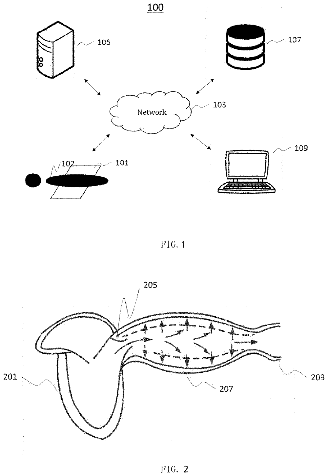
[0038]FIG. 1 is a schematic diagram of a pulse wave conduction parameter measurement system 100 in some embodiments of the present invention. As shown in FIG. 1, the pulse wave conduction parameter measurement system 100 can comprise a sensor device 101, a network 103, a server 105, a storage device 107, and an output device 109.

[0039]The sensor device 101 can be configured to acquire vibration information of the subject 102. In some embodiments, the sensor device 101 can be a vibration sensor, such as one or more of: an acceleration sensor, a speed sensor, a d...


PUM


Abstract

A pulse wave conduction parameter measurement system and method comprises: acquiring, by one or more processors, first vibration information of a supine subject from a first fiber optic sensor, the first fiber optic sensor being configured to be placed under a back region corresponding to the fourth thoracic vertebral body of the supine subject (step 711); acquiring, by the one or more processors, second vibration information of the supine subject from a second fiber optic sensor, the second fiber optic sensor being configured to be placed under a lumbar region corresponding to the fourth lumbar body of the supine subject (step 713); and generating, by the one or more processors, first hemodynamic related information on the basis of the first vibration information, and generating second hemodynamic related information on the basis of the second vibration information (step 715), thereby determining an aortic Pulse Wave Transit Time of the supine subject (step 719).

Description

FIELD OF THE INVENTION[0001]The present invention relates generally to the field of a pulse wave conduction parameter measurement system and method, and particularly relates to a non-invasive pulse wave conduction parameter measurement system and method.BACKGROUND OF THE INVENTION[0002]The description herein only provides background information related to the application, and do not necessarily constitute prior art.[0003]Worldwide, cardiovascular and cerebrovascular diseases are an important cause of morbidity and death, and morbidity and death caused by cardiovascular and cerebrovascular diseases are related to arterial vascular diseases. For example, angina pectoris and myocardial infarction are related to coronary artery disease; stroke is related to cerebral artery disease, and intermittent claudication is related to lower extremity arterial disease. The two main types of arterial lesions include structural lesions and functional lesions. Structural lesions are manifested as vas...

Claims


Application Information

Patent Timeline
Patent Type & Authority Applications(United States)
IPC IPC(8): A61B5/021A61B5/00G01H9/00
CPCA61B5/02125A61B5/7239G01H9/004A61B5/6892A61B5/6822
Inventor ZHUANG, SHAOCHUNYE, FEICHEN, RENKU
Owner SHENZHEN DARMA TECH CO LTD
Why Eureka
Try Eureka