Multi-lane serializer device

a serializer and multi-lane technology, applied in the direction of synchronisation signal speed/phase control, code conversion, baseband system details, etc., can solve the problem that the phase difference between the first clock and the load signal cannot be recovered within the appropriate range, the bit error rate of the received data is high, and the error occurs in the serial data output. problem, to achieve the effect of reducing the bit error rate, simple configuration and reducing the ips

Active Publication Date: 2021-07-29
THINE ELECTRONICS
View PDF0 Cites 2 Cited by
  • Summary
  • Abstract
  • Description
  • Claims
  • Application Information

AI Technical Summary

Benefits of technology

[0019]According to the present invention, it is possible to reduce the bit error rate at an early stage with a simple configuration in each serializer circuit and reduce the IPS between the serializer circuits of a plurality of lanes.

Problems solved by technology

When the phase difference between the first clock and the load signal deviates from the appropriate range due to a malfunction caused by noise or a temperature change, an error occurs in the serial data output from the serializer circuit.
When a receiver that receives the serial data output from the serializer circuit detects that the bit error rate of the received data is high, the receiver notifies the serializer circuit on the transmitting side that the bit error rate of the received data is high.
Therefore, in the serializer circuit, the phase difference between the first clock and the load signal cannot be recovered within the appropriate range.
Even if there is a communication line from the receiving side to the transmitting side, when the communication line is simple and slow, it takes a long time for the receiver to notify the serializer circuit on the transmitting side that the bit error rate is high.
Therefore, since it takes a long time to recover the phase difference between the first clock and the load signal within the appropriate range in the serializer circuit, the bit error rate continues to be high over a long period of time.

Method used


Image

  • Multi-lane serializer device
  • Multi-lane serializer device
  • Multi-lane serializer device

Examples


Embodiment Construction

[0026]Hereinafter, embodiments for carrying out the present invention will be described in detail with reference to the accompanying diagrams. In addition, in the description of the diagrams, the same elements are denoted by the same reference numerals, and the repeated description thereof will be omitted. The present invention is not limited to these examples, but is defined by the claims, and is intended to include all modifications within the meaning and scope equivalent to the claims.

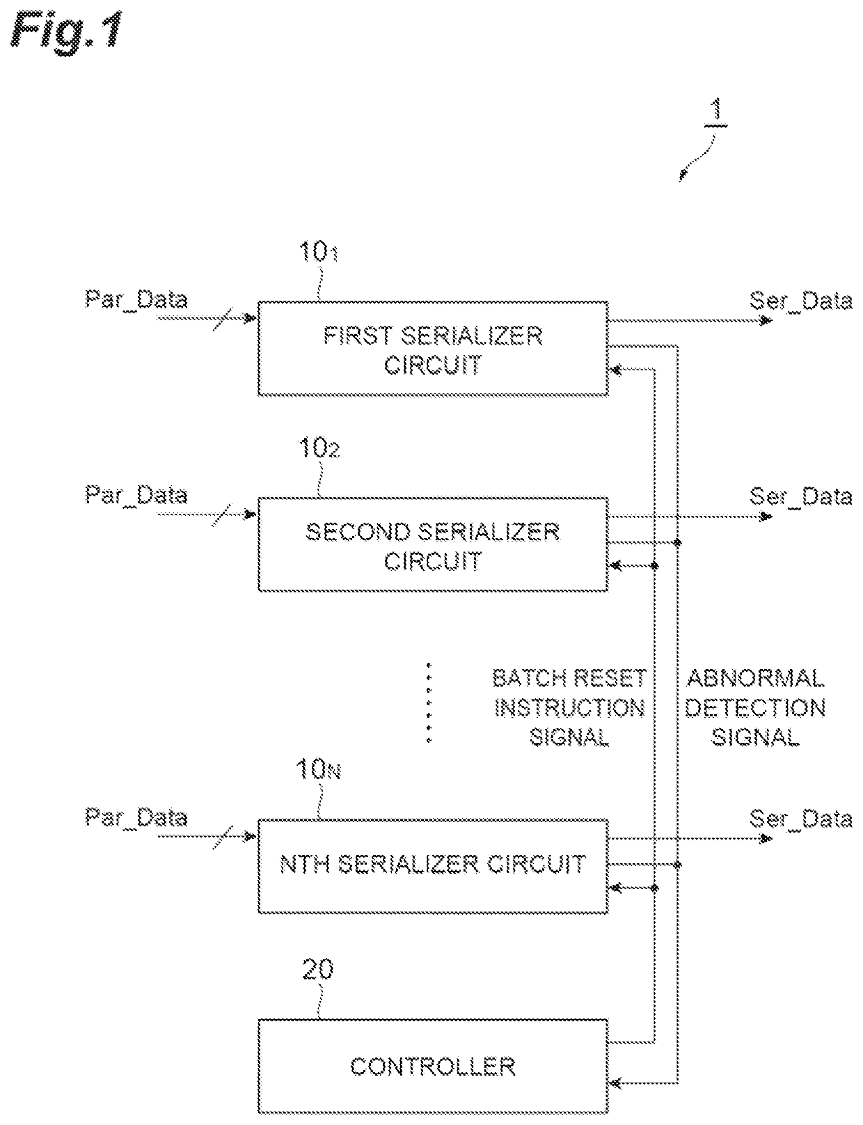
[0027]FIG. 1 is a diagram illustrating the configuration of a multi-lane serializer device 1. The multi-lane serializer device 1 includes a plurality of serializer circuits 101 to 10N and a controller 20. Each serializer circuit 10n serializes parallel data Par_Data that is input in synchronization with a first clock CLK1, and outputs serial data Ser_Data in synchronization with a second clock CLK2. N is an integer of 2 or more, and n is an integer of 1 or more and N or less. Each serializer circuit...


PUM


Abstract

A multi-lane serializer device 1 includes serializer circuits 101 to 10N and a controller 20. A phase difference detector of each serializer circuit detects a phase difference between a load signal and a first clock, and outputs an abnormal detection signal to the controller 20 when the detected phase difference is abnormal. When the controller 20 receives the abnormal detection signal from any of the serializer circuits, the controller 20 transmits a batch reset instruction signal to all the serializer circuits. Then, in all the serializer circuits, when a reset signal generator receives the batch reset instruction signal output from the controller 20, the reset signal generator transmits a reset instruction signal to a load signal generator to reset the operation of a load signal generation in the load signal generator.

Description

TECHNICAL FIELD[0001]The present invention relates to a multi-lane serializer device including serializer circuits of a plurality of lanes.BACKGROUND ART[0002]A serializer circuit serializes parallel data that is input in synchronization with a first clock, and outputs serial data in synchronization with a second clock. The serializer circuit latches the parallel data at a timing indicated by a load signal having the same period as that of the first clock, and outputs the latched data as serial data in synchronization with the second clock. The period of the second clock is shorter than the period of the first clock. The load signal has the same period as the first clock, and is generated based on the second clock (refer to Patent Literature 1).[0003]In the serializer circuit, it is important that the phase difference between the first clock and the load signal is set within an appropriate range according to the margins of the setup time and the hold time during the latch operation ...

Claims


Application Information

Patent Timeline
Patent Type & Authority Applications(United States)
IPC IPC(8): H03M9/00H04L7/04H04L7/00
CPCH03M9/00H04L7/0012H04L7/042H04L25/02H04L7/0008H04L7/027H04L25/38
Inventor MIURA, SATOSHIFUJITA, YUSUKE
Owner THINE ELECTRONICS
Why Eureka
Try Eureka