Extremely electrically small antennas based on multiferroic materials

a multiferroic material and antenna technology, applied in the field of electricly small antennas, can solve the problems of antennas with significantly higher ohmic losses, low radiating capability of conventional antennas, and multiferroic antenna designs

Pending Publication Date: 2021-08-05
RGT UNIV OF CALIFORNIA
View PDF8 Cites 9 Cited by
  • Summary
  • Abstract
  • Description
  • Claims
  • Application Information

AI Technical Summary

Benefits of technology

[0010]The technology described in this disclosure generally pertains to radio frequency antennas, and more particularly, to a mechanical mediated multiferroic antenna for radio frequencies. Multiferroic antennas include th

Problems solved by technology

However, a conventional antenna exhibits low radiating capability when placed near a conductive plane due to a platform effect.
At the same time, when made into a small size, the antenna will have significantly

Method used


Image

  • Extremely electrically small antennas based on multiferroic materials
  • Extremely electrically small antennas based on multiferroic materials
  • Extremely electrically small antennas based on multiferroic materials

Examples


Embodiment Construction

1. Introduction

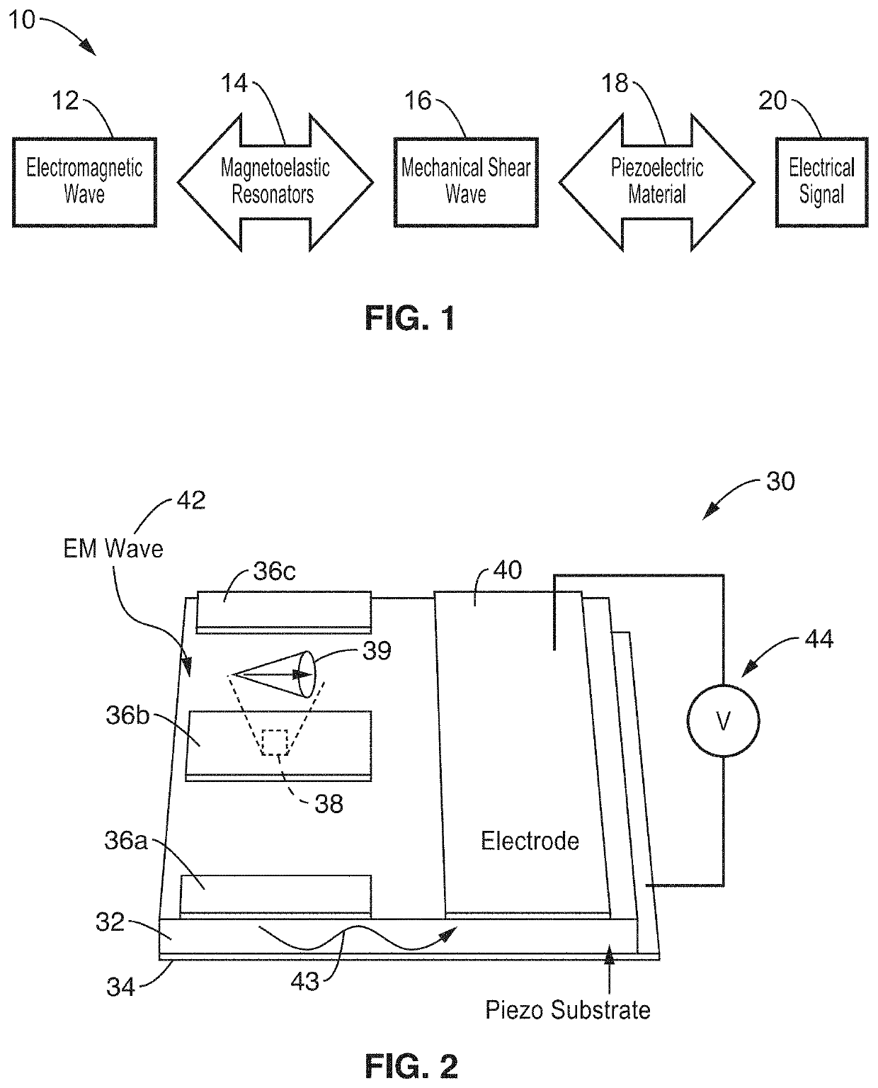
[0027]An antenna is described, by way of example and not limitation, which relies on magnetoelastic and / or magnetostrictive resonators to transmit electromagnetic waves through dynamic strain, or to receive electromagnetic waves when such a dynamic strain is induced on a piezoelectric substrate. The magnetoelastic and / or magnetostrictive resonators can only transfer certain frequency EM waves into mechanical vibrations related to their natural frequency of resonance. The size, shape, and distance relationship between the resonator and its receiver / detector electrode determine the resonant parameters, which are conditions for peak voltage detection. A feature of this antenna is that the resonators are in the same plane with the electrode detectors, but in a different plane with the ground electrode. The electrical field is applied out-of-plane and the strength of such a field is detected through measuring the induced voltage. In this way, the energy loss will be reduce...


PUM


Abstract

A multiferroic antenna apparatus and method are described which provides increased energy efficiencies and ease of implementation. Magnetoelastic and/or magnetostrictive resonator are coupled to a piezoelectric substrate, along with electrodes coupled to its opposing surfaces. In receive mode the resonators create mechanical waves in response to being excited into magnetic oscillation by receiving electromagnetic radiation, and these mechanical waves coupled to the piezoelectric substrate causing it to generate an electrical output signal at said electrodes. In transmit mode an electrical signal coupled through the electrodes induces mechanical waves in the piezoelectric substrate directed to the resonators which are excited into magnetic oscillation to output electromagnetic waves.

Description

CROSS-REFERENCE TO RELATED APPLICATIONS[0001]This application claims priority to, and is a 35 U.S.C. § 111(a) continuation of, PCT international application number PCT / US2019 / 045865 filed on Aug. 9, 2019, incorporated herein by reference in its entirety, which claims priority to, and the benefit of, U.S. provisional patent application Ser. No. 62 / 716,936 filed on Aug. 9, 2018, incorporated herein by reference in its entirety, and which also claims priority to, and the benefit of, U.S. provisional patent application Ser. No. 62 / 880,513 filed on Jul. 30, 2019, incorporated herein by reference in its entirety. Priority is claimed to each of the foregoing applications.[0002]The above-referenced PCT international application was published as PCT International Publication No. WO 2020 / 101773 A2 on May 22, 2020, which publication is incorporated herein by reference in its entirety.STATEMENT REGARDING FEDERALLY SPONSORED RESEARCH OR DEVELOPMENT[0003]This invention was made with government su...

Claims


Application Information

Patent Timeline
IPC IPC(8): H01Q21/06H01Q3/44
CPCH01Q21/067H01Q3/44H03H9/02228H03H9/175H01Q9/0407H01Q1/38
Inventor SEPULVEDA, ABDON E.CARMAN, GREGORY P.HU, JINZHAOSCHNEIDER, JOSEPH DEVINWU, ELMERYAO, ZHITIWARI, SIDHANTYAN, WENZHONG
Owner RGT UNIV OF CALIFORNIA
Why Eureka
Try Eureka