Rods and assemblies of rods for the collection and transportation of water

a technology of rods and rod assemblies, applied in the direction of sewage draining, ways, ground pavings, etc., can solve the problems of large water waste, blockage of structures, and significant water loss due to evaporation, and achieve the effect of high collection and discharge capacity

Pending Publication Date: 2021-08-12
TARAPASKI WILLIAM ERNEST
View PDF0 Cites 0 Cited by
  • Summary
  • Abstract
  • Description
  • Claims
  • Application Information

AI Technical Summary

Benefits of technology

[0022]The invention comprises a rod used for the collection and / or transportation of water wherein the rod is structured to maintain spacing with other similar-shaped rods. The rods may be laid in a trench, connected to a pipe, bound in prefabricated units, or arranged in a round shape for the collection and transport of water by capillary action. Since groundwater can move upwards by capillary from the bottom surface of an assembly of such rods, the collected and transported water is free from soil and debris. The spacing between adjacent rods results in a system having a high collection and discharge capacity.

Problems solved by technology

Such drainage systems typically utilize perforated pipes that are laid below the surface which are prone to clogging.
The practice does not selectively water desired areas or plants and therefore wastes large quantities of water.
Additionally, a significant percentage of water loss due to evaporation can occur with such current irrigation systems.
Flow and the accumulation of particle settlement can result in blockages of structures.
The collection of groundwater by excavating trenches and installing perforated pipes, with or without drain rock, simply transfers surface water behaviours below the surface, along with the clogging problems associated with flow.
Moreover, a known problem is that there is a considerable migration of soil particles into the voids created by the larger drain rock aggregate.
Except for filters, there has been little innovation to drainage methods.
However even filters, as expected, clog from the particles that they block and eventually require replacement.
Typically, filters cannot be changed without a complete reconstruction which is often a more expensive undertaking than the original construction.
Since flow is a surface behaviour, the installation of flow mechanisms underground will cause erosion resulting in blocked pipes and filters as the displaced particles build up within the structure.
The vertical migration of the water into the channels separates any soil particles from the water since water migration by capillary cannot transport soil particles when the soil is in a settled state.
While the wide belt assembly advanced the effective collection of water free of soil particles, it also had limitations.
The small size of the collection channels limited both the capacity for the collection and discharge of water and the transport of water to a discharge point.
Preparation of a drain belt and pipe assembly also required extensive time and effort.
Additionally, the drain belt of the prior art is thin and soft, which means that it requires proper support.
The complicated contouring and compaction requirement is often not appreciated by installation teams which results in excessive settlement after installation, negative slope, and poor performance.
While such products can collect and transport water by capillary, there is no arrangement to separate soil particles from the water.
Over time, fine soil particle will fill and block the pore space of the wick and reduce its performance.
Rather than using an internal cavity which is very limiting with regards to capacity, the water is collected in the spaces between parallel members.
While the principle of parallel spaced rods and layers of spaced rods works well, manufacturing the assembly disclosed in Tarapaski on a large scale is impractical from a cost perspective.
A complex array of spacing and joining methods coupled with the incompatibility of container shapes to normal pipe networks makes it unlikely that this assembly will be manufactured and used to any significant degree.
However, the desGarennes system functions essentially as a wick and uses a filter that will ultimately trap soil particles and lead to clogging problems.

Method used


Image

  • Rods and assemblies of rods for the collection and transportation of water
  • Rods and assemblies of rods for the collection and transportation of water
  • Rods and assemblies of rods for the collection and transportation of water

Examples


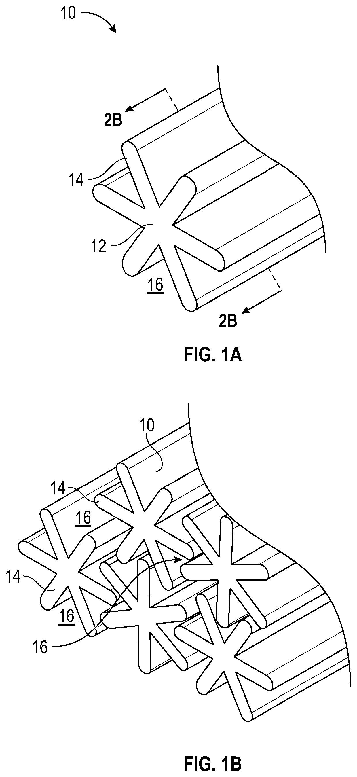
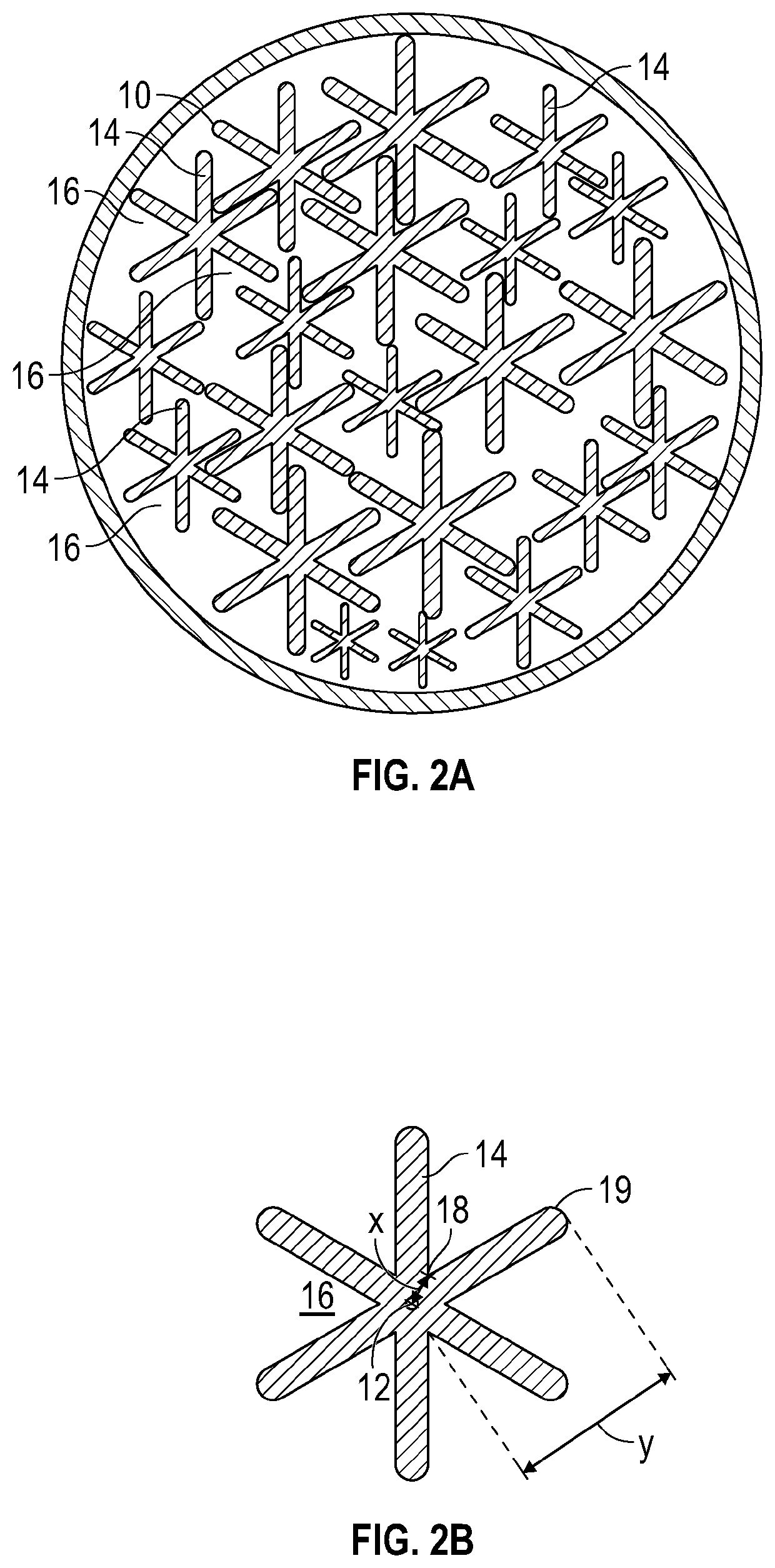
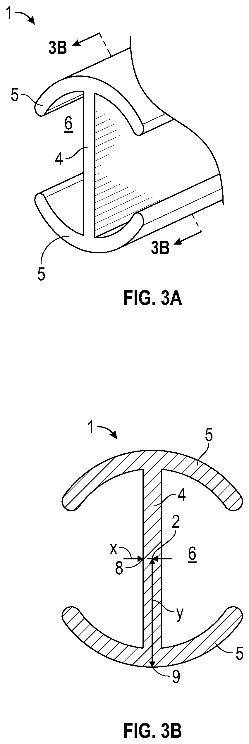
Embodiment Construction

)

[0074]The inventor has tested an exact model of the most common drainage assembly, namely a perforated pipe surrounded by drain rock. The test revealed results that are inconsistent with expectations. A model with holes in the bottom was used to indicate when water passed through the testing assembly instead of being collected in the perforated pipe. During the test, despite a steady steam of water coming out of the bottom of the model, there was no water in the pipe. An actual construction of a drainage pipe confirmed that water does not enter the pipe to any significant level; instead, the water flows through the drain rock surrounding the pipe. The results are consistent with flow behaviour of water.

[0075]Water can only enter the perforated pipe when the flow path becomes blocked and the groundwater level rises. The rising water creates pressure to force the water through the perforations in the pipe. This observed behaviour verifies that the source for drainage collection is fr...


PUM


Abstract

A rod for collecting water or transporting water structured to result in capillary spaces between it and other similar-shaped rods when such rods are adjacent to one another. The rod has a cross-sectional shape with one surface portion of the rod being a greater distance from the center of the rod than another surface portion of the rod. The rods can be laid together in an assembly or prefabricated into an assembly that provides an efficient, high capacity water collection and / or transportation system that is resistant to clogging.

Description

FIELD OF THE INVENTION[0001]This invention relates to a water collection and transportation apparatus and method. In particular, this invention relates the use of assemblies of shaped rods having spaces between the rods for the efficient collection of particle free water from soil by capillary and / or for the transport of particle free water to a discharge point.BACKGROUND OF THE INVENTION[0002]Systems for collecting and distributing water are critical in many different industries and fields. For instance, sports fields and golf courses require water drainage systems that collect and move water away from wet areas. Such drainage systems typically utilize perforated pipes that are laid below the surface which are prone to clogging.[0003]Water resources are also increasingly under pressure from various interests worldwide. Traditionally, irrigation systems utilize large pumps to spray vast quantities of water, blanketing an area. The practice does not selectively water desired areas or...

Claims


Application Information

Patent Timeline
Patent Type & Authority Applications(United States)
IPC IPC(8): E02B11/00E03F1/00A01G29/00A01G25/02
CPCE02B11/005E03F1/002E01C13/083A01G25/02A01G29/00E02B11/00E01C11/227E01C13/02
Inventor TARAPASKI, WILLIAM ERNEST
Owner TARAPASKI WILLIAM ERNEST
Why Eureka
Try Eureka