Simulation device, simulation method, and ecu device

a simulation device and simulation method technology, applied in the direction of geometric cad, design optimisation/simulation, instruments, etc., can solve the problems of only occurring in one environment, the number of hardware prototypes assigned to software developers is often small, etc., to ensure the quality of software in the upstream process

Pending Publication Date: 2021-08-12
HITACHI ASTEMO LTD
View PDF2 Cites 1 Cited by
  • Summary
  • Abstract
  • Description
  • Claims
  • Application Information

AI Technical Summary

Benefits of technology

[0020]According to the present invention, the execution timing in the PC simulation environment can be adjusted to be closer to the execution timing in the actual ECU. Since the timing adjustment can be performed for each PC, the delay amount can be adjusted for each PC environment of a developer.
[0021]Further, according to the embodiments of the present invention, software can be verified in an environment in which a processing timing that is close to a processing timing in an actual ECU is realized even when the number of actual ECU prototypes during development is small, and thus it is possible to assist in ensuring the quality of software in the upstream process.

Problems solved by technology

Further, even after a hardware prototype is prepared, the number of hardware prototypes assigned to a software developer is often small.
Due to a difference in execution timing of the application software between the PC environment and the actual ECU environment, malfunction that occurs only in one of the environments occurs.
In addition to the difference between the PC environment and the actual ECU environment, the specification of the PC used in development often differs between developers, which causes a situation that occurs only in an actual ECU and a specific PC.

Method used


Image

  • Simulation device, simulation method, and ecu device
  • Simulation device, simulation method, and ecu device
  • Simulation device, simulation method, and ecu device

Examples


embodiment 1

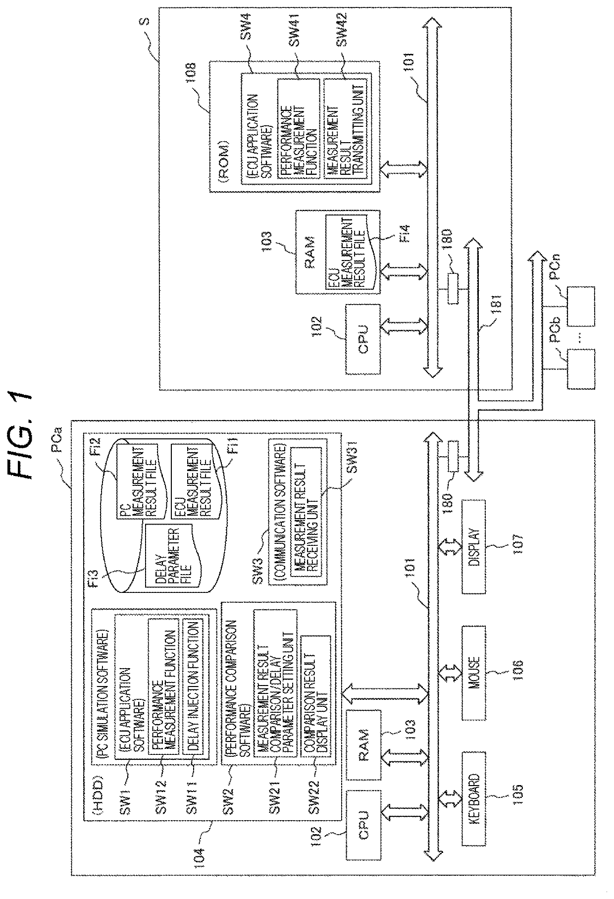
[0046]In Embodiment 1, particularly, the hardware configuration of the simulation device will be mainly described. FIG. 1 is a diagram illustrating an example of configurations of the actual ECU environment and the PC environment in the simulation device of the present invention.

[0047]The right side of FIG. 1 illustrates an example of a configuration of an actual environment machine S that realizes the actual ECU environment, and the left side of FIG. 1 illustrates an example of a configuration of the PC that realizes the PC environment. The actual environment machine S and a plurality of PCs (PCa, PCb, . . . , and PCn) are connected to an external system bus 181 via a communication device 180. Since the PC basically has the same configuration and function, the PC PCa will be described below as a representative example.

[0048]Since the actual environment machine S and the PC are both implemented by a computer system, in hardware configurations thereof, as well known, a central proces...

embodiment 2

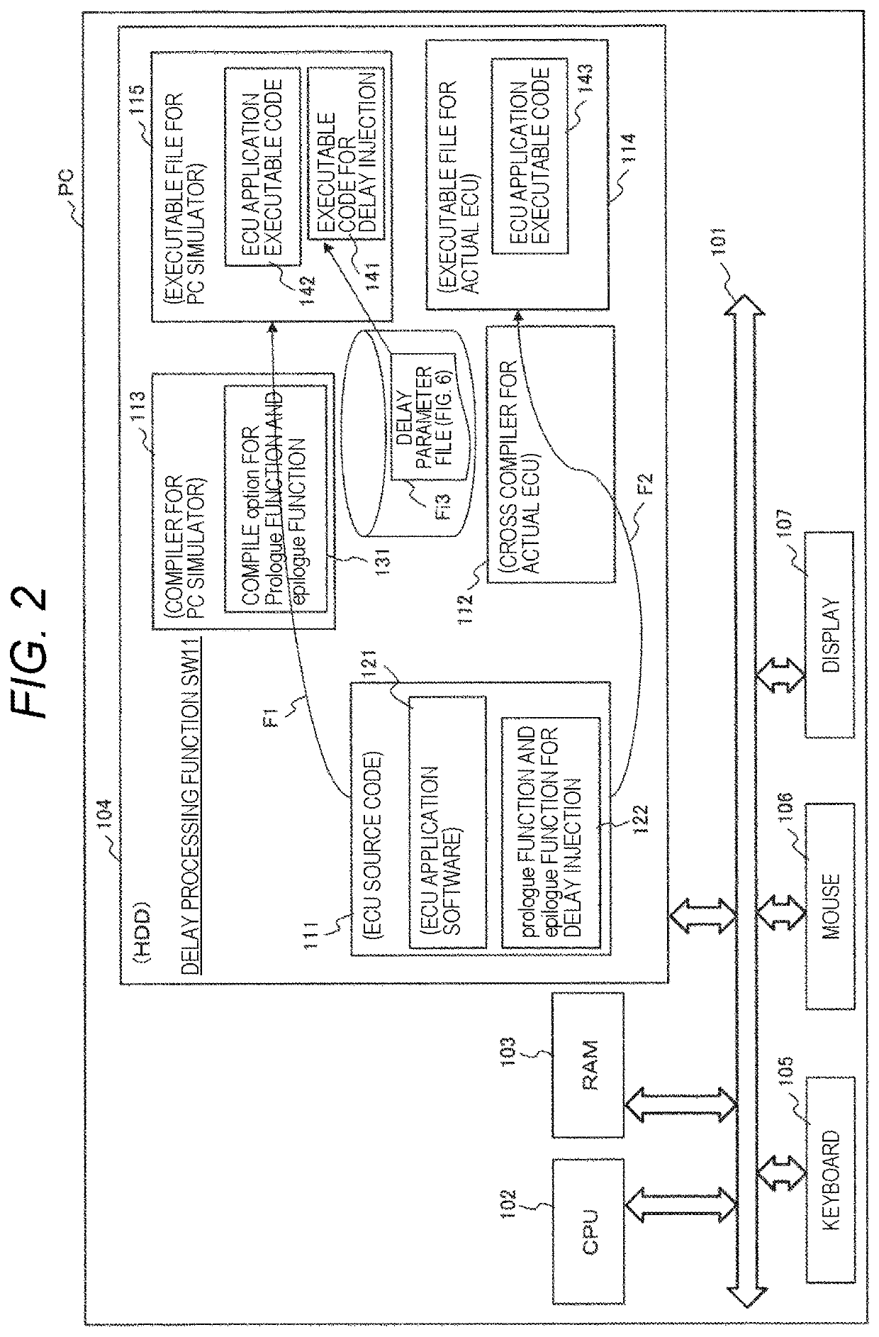
[0055]In the description of Embodiments 2 to 5 of the present invention, the hardware configuration and main processing functions of the PC that implements the simulation device, the hardware configuration and main processing functions being particularly related to the delay injection function Sw11, will be described. In addition, a generation process in which software to be ported to the ECU device is created by using the simulation device will be described.

[0056]First, the hardware configuration and main processing functions of the PC that implements the simulation device will be described with reference to FIG. 2, the hardware configuration and main processing functions being particularly related to the delay injection function Sw11.

[0057]As described in FIG. 1, the simulation device of FIG. is implemented by a general PC, and in the hardware configuration thereof, the CPU 102, the main storage device (RAM) 103, the hard disk drive (HDD) 104, the keyboard 105, the mouse 106, the ...

embodiment 3

[0100]In Embodiment 2, the delay time is set at the front part or rear part of each function to perform timing matching with the ECU on the assumption that a processing speed of the ECU is lower than a processing speed of the PC. That is, the delay processing is performed as the time adjustment processing.

[0101]On the other hand, the processing speed of the ECU may be higher than the processing speed of the PC. FIG. 8 is a diagram illustrating an example of a timing in a case where the processing speed of the ECU is higher than the processing speed of the PC. FIG. 8 illustrates a countermeasure for such a case. For example, a case where the ECU requires AtE1 for processing of the Main function, and the PC requires more time is assumed. In this case, it is preferable to adjust the time required for the processing of the Main function in the PC to be the same as the processing time of AtE1 in the ECU by multiplying the time required for the processing of the Main function in the PC by...


PUM


Abstract

An object of the present invention is to provide a simulation device that can adjust an execution timing in a PC simulation environment to be closer to an execution timing in an actual ECU by using a simple method, a simulation method, and an ECU device. A simulation device includes: a first computer including a first performance measurement function that obtains a first processing timing when the first computer executes application software, and a timing adjustment function that performs timing adjustment of an execution time of the application software in the first computer based on a time difference between the first processing timing and a second processing timing when a second computer executes the application software.

Description

TECHNICAL FIELD[0001]The present invention relates to a simulation device having a function of adjusting an execution timing, a simulation method, and an ECU device, for example, a simulation device used by a developer during development of software of an electronic control unit (ECU) of an automobile, a simulation method, and an ECU device.BACKGROUND ART[0002]In the development of software for ECUs, there are few cases where a hardware prototype is prepared at an early stage of the development. Therefore, in general, after designing software on a personal computer (PC), operation checking is performed in a PC environment (simulation environment), the software verified in the PC environment is ported to an actual ECU environment that is a hardware prototype, and then operation checking is performed.[0003]Further, even after a hardware prototype is prepared, the number of hardware prototypes assigned to a software developer is often small. For example, one hardware prototype may be s...

Claims


Application Information

Patent Timeline
Patent Type & Authority Applications(United States)
IPC IPC(8): G06F30/20
CPCG06F30/20G06F2119/12G06F11/3419G06F2201/865G06F11/302G06F11/3664G06F11/3668G06F30/15
Inventor MURASHIMA, YASUNORIFUKUSHIMA, YUJINARISAWA, FUMIO
Owner HITACHI ASTEMO LTD
Why Eureka
Try Eureka