Check patentability & draft patents in minutes with Patsnap Eureka AI!

Bale Severance Mechanism for a Continuous Round Baler

Pending Publication Date: 2021-08-19
MCHALE ENG
View PDF10 Cites 0 Cited by
  • Summary
  • Abstract
  • Description
  • Claims
  • Application Information

AI Technical Summary

Benefits of technology

This patent describes a continuous round baler that can create round bales of crop without the need for a second chamber to form a bale or accumulate crop while the baler is in use. The baler is also designed to be durable, inexpensive, easy to assemble, and simple to use. The technical effects of this patent are a more efficient and effective baler that can create larger bales of crop without the need for a separate chamber and is easy to assemble and use.

Problems solved by technology

However, all of these conventional round balers eventually had to cease temporarily the operation of collecting crop material so that the fully formed bale could be ejected from the machine.
Thus, the conventional round balers did not have the advantage of the rectangular balers in being able to continuously move over the surface of the field to collect crop material therefrom.
1. There is an operational time loss to wrap and eject the bale from the baler.
2. Expensive and complicated mechanisms are required to form and then quickly eject the formed bale. Some round baler manufacturers have spent considerable effort to obtain a 3-5 second reduction in time for ejecting the bale from the round baler.
3. For balers that utilize belts, belt tracking and durability are problems, particularly for the more complicated continuous round balers. With multiple belts, and especially with long multiple belts, problems are encountered with manufacturing consistency and with utilization of the belts in different crop conditions. Belts that travel over rollers have an inherent problem of crop wrapping around the rollers and forcing the belts out of engagement with the rollers.
4. Maintaining a uniform cylindrical bale shape requires the operator to weave the round baler back and forth laterally over the crop windrow so that an even amount of hay will be maintained at both ends of the round bale.
5. Net wrapping systems are complicated and use heavy rolls of netting material that have to be lifted and loaded into an elevated receptacle on the baler.
6. Crop loss, particularly those very valuable leaves and other fines, leak from the baler during operation and are lost from the baling process and fall to the ground.
This two chamber concept theoretically solved the first problem noted above to end the operational time loss, but worsened the second problem noted above, as this was a very big, heavy, complicated and expensive machine.
This Bowden machine encountered problems of the newly formed bale in the front chamber growing too fast while the formed bale was being ejected, which was particularly true in heavy crop conditions.
This Roberge machine appears to be very heavy and very complex.
The problem with this design is that the accumulation chamber has to be very large, especially if accumulating loose crop and operating in heavy crop windrows.
Slowing the machine defeats the original reason for having the accumulation chamber which is to speed up the production.
This Krone machine also incorporates the accumulation chamber concept and the accumulation of loose hay is a difficult thing to properly manipulate.
This Krone machine is very large and very complex.
While technically the baler does not stop moving in a forward direction, these two chamber concepts are not a truly continuous bale formation process.
Furthermore, each of these configurations suffer from the same disadvantages in that the tailgate of the baler must be opened, raising the center of gravity of the machine and adding stress on the structural components, while the baler is being moved along the surface of the field.
Furthermore, the operation of a round baler utilizing an accumulation chamber to store collected crop material while the round baler performs the non-bale forming functions of the conventional round baler does not create a truly continuously operable round baler in the same sense as a rectangular baler is continuously operable.

Method used


Image

  • Bale Severance Mechanism for a Continuous Round Baler
  • Bale Severance Mechanism for a Continuous Round Baler
  • Bale Severance Mechanism for a Continuous Round Baler

Examples


Embodiment Construction

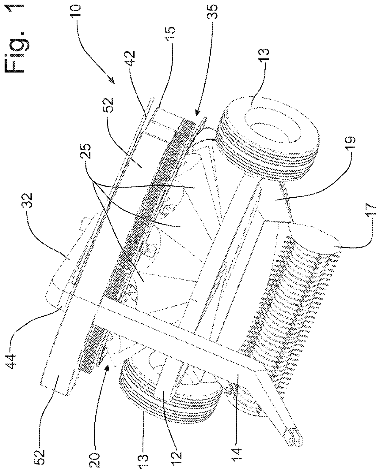
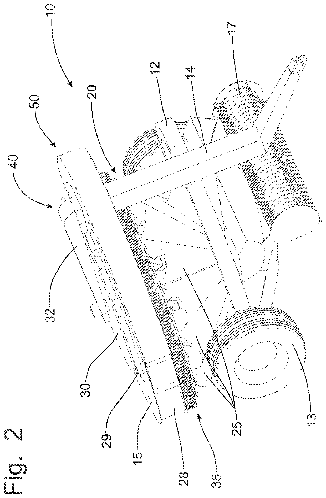
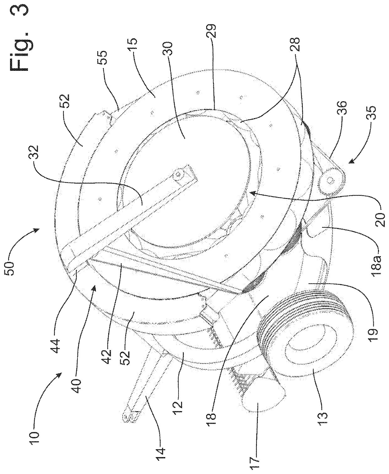
[0108]Referring now to drawings, a continuous round baler incorporating the principles of the instant invention can best be seen. Any references to left, right, front and rear are determined by standing at the rear of the machine facing a prime mover, such as a tractor, that is connected to pull the continuous round baler in a forward direction behind the prime mover. The continuous round baler 10 includes a wheeled frame 12 having a pair of laterally spaced ground engaging wheels 13 and a forwardly extending draft tongue 14 that is connectable to a prime mover (not shown), such as a tractor, that provides a source of rotational power and a source of hydraulic power in a conventional manner.

[0109]The frame 12 further includes a circular roller support member 15 to rotatably support the rollers 28 in the bale chamber 20 as will be described in greater detail below. The draft tongue 14 connects to the roller support member 15 and provides a hollow receiver for the support beam 32 supp...


PUM


Abstract

A continuous round baler forms a cylindrically-shaped bale by spiral, coiled layers created by a conical portion of a bale-forming chamber and protruded upwardly from a cylindrical portion of the bale-forming chamber. The bale is circumferentially supported by netting applied to the bale in the cylindrical portion. A rotary feed table receives crop from the field and feeds the crop into the conical portion. The bale forming process can be interrupted if an insufficient volume of crop is collected on the rotary feed table. The netting material is provided on short rolls to facilitate loading onto the machine. A cutoff mechanism is coupled to the growth of the bale from the cylindrical portion to sever the bale at a predetermined length with end surfaces that are perpendicular to the axis of the bale. A bale density mechanism supports the distal end of the bale as the bale protrudes upwardly.

Description

CROSS-REFERENCE TO RELATED APPLICATIONS[0001]This application claims domestic priority on U.S. Provisional Patent Application Ser. No. 62 / 086,594, filed on Dec. 2, 2014, and on U.S. Provisional Patent Application Ser. No. 62 / 111,884, filed on Feb. 4, 2015, the contents of which are incorporated herein by reference.FIELD OF THE INVENTION[0002]This invention relates generally to the formation of cylindrical bales of crop material in the field and, more particularly, to a round baler that is operable to move across a field to continuously collect crop material for the formation of a round baler without stopping to eject the round bale from the machine.BACKGROUND OF THE INVENTION[0003]The baling of agricultural crop material has traditionally been done with rectangular balers that formed compressed bales of crop material, such as forage crop material, that could be handled manually. As farming operations became more mechanized, the sizes of the bales of crop material increased with some...

Claims


Application Information

Patent Timeline
IPC IPC(8): A01F15/07A01F15/08
CPCA01F15/0705A01F2015/0755A01F2015/074A01F15/0883A01F15/0715
Inventor UNDERHILL, KENNETH R.
Owner MCHALE ENG
Features
  • R&D
  • Intellectual Property
  • Life Sciences
  • Materials
  • Tech Scout
  • Unparalleled Data Quality
  • Higher Quality Content
  • 60% Fewer Hallucinations
Learn More