
Device for implanting a prosthesis for a heart valve and assembly procedure

a heart valve and prosthesis technology, applied in the field of heart valve prosthesis implanting device and assembly procedure, can solve the problems of reducing efficiency, complex and delicate heart valve organs, and high impairing valve pathology

Pending Publication Date: 2021-08-19
RIGHINI GIOVANNI +4
View PDF0 Cites 0 Cited by
  • Summary
  • Abstract
  • Description
  • Claims
  • Application Information

AI Technical Summary

Benefits of technology

The invention provides a device and procedure for implanting a heart prosthesis through a transcatheter procedure with transseptal access. This device and procedure help prevent damage to the apex of the heart and are safer for the patient. The device includes a guidewire introducer and a device for implanting the heart prosthesis, which are reliable and safe for use. Additionally, the procedure allows for the assembly of the heart prosthesis using this device for implantation.

Problems solved by technology

Heart valves are complex and delicate organs which govern the correct function of the human heart.
Among these, the insufficiency of the mitral valve, that is to say, the incapacity thereof to close completely, is a valve pathology which is highly impairing because it reduces the efficiency of the pumping action at the left side of the heart, which is responsible for blood circulation for the entire body.
Notwithstanding the refinement of the techniques for managing the cardiac arrest and improving the extracorporeal circulation systems, the therapy in open heart conditions presents risks as a result of the invasive nature thereof and the duration of the procedure.
In some cases, it is not even possible to intervene surgically as a result of the general conditions of the patient, for example, due to advanced age or the presence of concomitant pathologies.
The complex anatomical configuration of the valve and of the structures which surround it, the variability of the pathologies, also very different from each other, which affect the valve directly or indirectly, make extremely difficult to comply with the requirements for a reliable and effective implantation in a mitral valve via the transcatheter route.
A problem of this approach is that it brings about damage to the heart in a rather delicate portion, such as the apex, with consequences that can be detrimental to the patient, such as bleeding, aneurisms, etc.

Method used


Image

  • Device for implanting a prosthesis for a heart valve and assembly procedure
  • Device for implanting a prosthesis for a heart valve and assembly procedure
  • Device for implanting a prosthesis for a heart valve and assembly procedure

Examples


Embodiment Construction

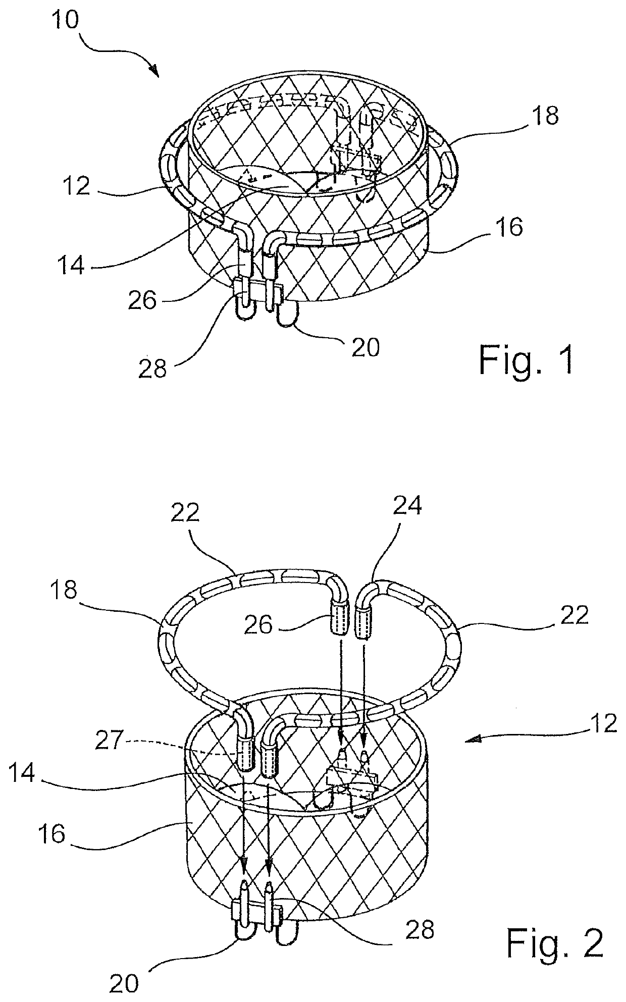
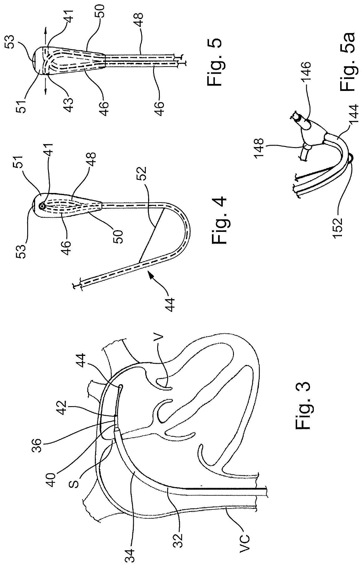
[0069]Now with reference to the drawings, in FIGS. 1 and 2 there is described an implantable heart prosthesis 10 which is used to replace the functionality of an atrio-ventricular valve.

[0070]The heart prosthesis 10 comprises a prosthetic structure 12 for support and interfacing with the native valve and by a group of flexible prosthetic leaflets 14 which are fixed therein. The prosthetic structure 12 comprises in particular:[0071]a central body 16,[0072]a containment portion 18,[0073]connecting elements 20 for connecting the central body 16 and the containment portion 18.

[0074]The prosthetic structure 12, as for each of the elements thereof, is configured so as to be collapsible without any consequence for the safety and the functionality of the heart prosthesis. Therefore, it is possible to temporarily reduce the radial dimensions of the prosthesis in order to allow the introduction thereof inside the cardiac cavities through access ports which have a reduced aperture and which ar...


PUM


Abstract

A device for implanting a heart prosthesis including a central body, a containment portion having one or more sub-components, and a release device for the central body capable of being inserted into a catheter. A device for assisting the connection operation between the central body and the sub-components of the containment portion includes an assembly of catheters, of which there are at least two catheters for each sub-component of the containment portion, the catheters being joined to each other over a portion thereof and having at least one free end for each catheter.

Description

CROSS-REFERENCE TO RELATED APPLICATIONS[0001]This is a divisional of prior U.S. Ser. No. 16 / 522,164, filed Jul. 25, 2019, the entire contents of which is hereby incorporated by reference herein in its entirety.FIELD OF THE INVENTION[0002]The present invention relates to a device for implanting a prosthesis for a heart valve and an assembly procedure.[0003]The invention has been developed with particular regard, though in a non-limiting manner, for a device for use during a procedure for implanting a heart prosthesis for replacing the physiological function of a malfunctioning heart valve and in particular a heart prosthesis for an atrio-ventricular heart valve.TECHNOLOGICAL BACKGROUND[0004]Heart valves are complex and delicate organs which govern the correct function of the human heart. The main objective thereof is to make the blood flow inside the cardiac cavities unidirectional, being essential both in the filling phase of the cavity, the diastolic phase, and in the discharge pha...

Claims


Application Information

Patent Timeline
Patent Type & Authority Applications(United States)
IPC IPC(8): A61F2/24A61M25/00
CPCA61F2/2412A61F2/2409A61F2/243A61F2210/0014A61F2/2436A61M2025/0024A61F2220/0016A61M25/0026A61F2/2418A61F2220/0033A61F2250/006
Inventor RIGHINI, GIOVANNITRINH, CINDYSHIN, DONG IKDENISON, ANDYMAGRINI, KEVIN
Owner RIGHINI GIOVANNI
Learn More