Active front wheel deflector assembly

a front wheel and active technology, applied in the direction of vehicle body stabilisation, transportation and packaging, windows, etc., can solve the problems of not meeting desired requirements, affecting the aerodynamic efficiency of fixed panels or fixed air deflectors/dams using flexible materials, and affecting the aerodynamic efficiency of vehicles. , to achieve the effect of less packaging space, improved aerodynamics, and optimized heigh

Active Publication Date: 2021-08-19
MAGNA EXTERIORS INC
View PDF2 Cites 0 Cited by
  • Summary
  • Abstract
  • Description
  • Claims
  • Application Information

AI Technical Summary

Benefits of technology

[0006]There is provided an aerodynamic surface which improves aerodynamics when deployed and is retractable out of the way to return the vehicle to its initial design intent. In particular, an active front wheel deflector assembly including linear actuation with rotational motion.
[0007]The Active front wheel deflector is moveable, thus, the height can be optimized. The active front wheel deflector assembly of the present invention with rotational motion requires less packaging space than the linear motion ones. The active front wheel deflector assembly compared to fixed or other front air deflectors, provides more benefits and applicable to a wider range of vehicles.

Problems solved by technology

There is a considerable loss of aerodynamic efficiency in vehicles due to the airflow underneath the vehicle and in front of the front wheels.
Conventional structures, such as fixed panels or fixed air deflectors / dams using flexible materials, are known and do not meet desired requirements that is durable and aerodynamically effective.
These fixed air deflector / dams are still a compromise as they cannot be made to the optimum height without compromising specifications and compromising to other vehicle capabilities.
Further, these air dams, even when flexible, are still damaged during off-roading or when added ground clearance is needed.
Further, these dams do not offer active wheel spats or combination of deflective panel and wheel spats selectively deployed individually or together, when desired.
In general, pressure in front of the tires increases drag, causing more fuel consumption.
Traditional tire deflectors can only extend a certain height due to styling, damageability and other constraints.
Known fixed wheel deflectors are limited as to height and shape, e.g., due to ground clearance parameters.
Conventional active air deflectors are not close to front wheels and limited as to package space.

Method used


Image

  • Active front wheel deflector assembly
  • Active front wheel deflector assembly
  • Active front wheel deflector assembly

Examples


Embodiment Construction

[0017]The following description of the preferred embodiment(s) is merely exemplary in nature and is in no way intended to limit the invention, its application, or uses.

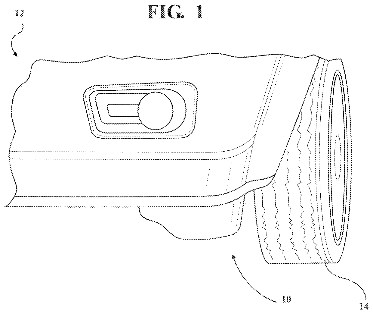
[0018]Referring to FIGS. 1-8 generally, there is depicted an active front wheel deflector assembly, shown generally at 10, operably mounted to the vehicle 12 adjacent to, preferably substantially in front of, the front tires 14 of the vehicle 12. The assembly 10 improves vehicle aerodynamics by smoothing the flow of turbulent air in front of the tires and the underbody airflow.

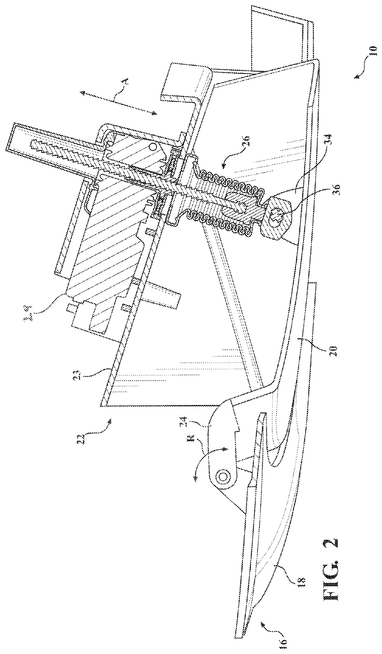
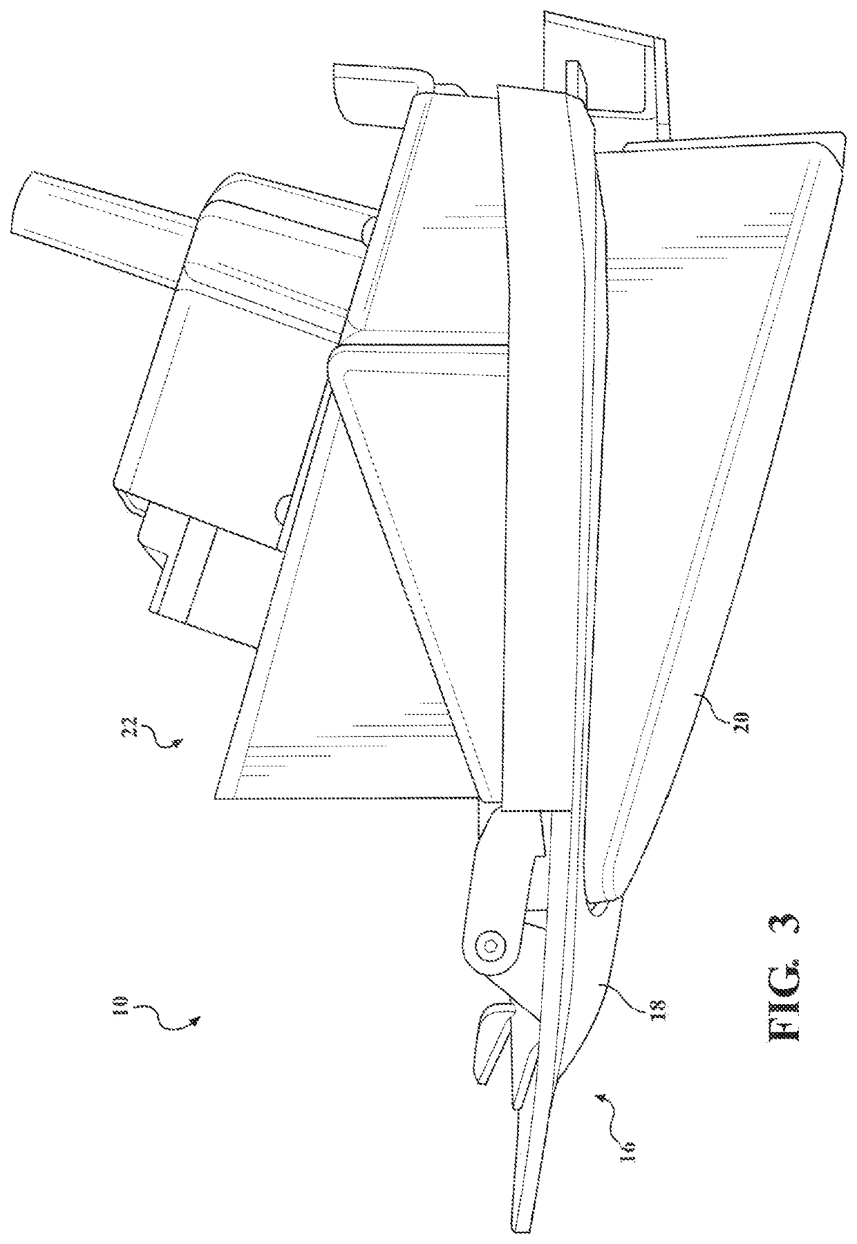
[0019]The active front wheel deflector assembly 10 provides a linear actuator combined with a rotational motion. A deflector portion 16 including at least one deflector is provided. Preferably, the deflector portion 16 includes at least one first panel 18, most preferably a static panel, and at least one second panel 20 that is a movable deflector. At least the second panel 20 is moveable to at least one predetermined height in a deployed positi...


PUM


Abstract

An active front wheel deflector assembly (10) including a deflector panel (20) moveable between a stowed position and at least one deployed position wherein the deployment of the deflector panel (20) moves the deflector panel (20) into an airflow to direct air and improves aerodynamics. The active front wheel deflector assembly (10) combines linear actuation with rotational motion.

Description

CROSS-REFERENCE TO RELATED APPLICATIONS[0001]This application is a PCT International Application and claims benefit of U.S. Provisional Patent Application No. 62 / 686,271, filed Jun. 18, 2019. The disclosure of the above application is incorporated herein by reference.FIELD OF THE INVENTION[0002]The present invention relates to an active front wheel deflector including linear actuation with rotational motion for automotive applications.BACKGROUND OF THE INVENTION[0003]There is a considerable loss of aerodynamic efficiency in vehicles due to the airflow underneath the vehicle and in front of the front wheels. Conventional structures, such as fixed panels or fixed air deflectors / dams using flexible materials, are known and do not meet desired requirements that is durable and aerodynamically effective. These fixed air deflector / dams are still a compromise as they cannot be made to the optimum height without compromising specifications and compromising to other vehicle capabilities. Furt...

Claims


Application Information

Patent Timeline
Patent Type & Authority Applications(United States)
IPC IPC(8): B62D35/00B62D37/02
CPCB62D35/005B62D37/02B62D35/02Y02T10/88Y02T10/82B60J10/72B60J10/767B60J1/20B62D35/008
Inventor WANG, YAOMAY, JEFFREY E.COBB, THOMAS E.MATTHEWS, MARTIN R.LINDBERG, BRAENDON R.
Owner MAGNA EXTERIORS INC
Why Eureka
Try Eureka