Image heating device, image forming apparatus, and heater

a heating device and heating device technology, applied in the direction of ohmic-resistance heating details, electrographic process devices, instruments, etc., can solve the problems of longitudinal non-uniformity in fixing performance and gloss, and achieve the effect of high-precision temperature control

Active Publication Date: 2021-08-19
CANON KK
View PDF0 Cites 3 Cited by
  • Summary
  • Abstract
  • Description
  • Claims
  • Application Information

AI Technical Summary

Benefits of technology

[0026]According to the present invention, highly accurate temperature control is made possible.

Problems solved by technology

As described above, when the positional relations between the control thermistor and the heat-generating resistor are different depending on the heat-generating block, if temperature control is executed at the same temperature, a difference is generated in average temperatures among the heat-generating blocks as illustrated in FIG. 12C, and there is a possibility that longitudinal non-uniformity can occur in fixing performance and gloss.

Method used


Image

  • Image heating device, image forming apparatus, and heater
  • Image heating device, image forming apparatus, and heater
  • Image heating device, image forming apparatus, and heater

Examples


embodiment 1

[0042]1. Constitution of Image Forming Apparatus

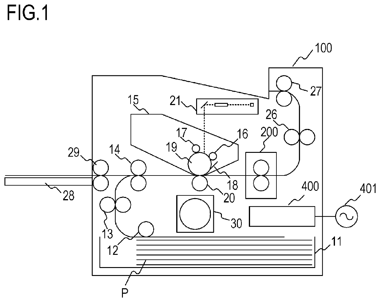
[0043]FIG. 1 is a schematic sectional view of an image forming apparatus according to an embodiment 1 of the present invention. The image forming apparatus 100 in this embodiment is a laser printer for forming an image using the electrophotographic system.

[0044]When a print signal is generated, a laser beam modulated in accordance with image information is emitted by a scanner unit 21, and a surface of a photosensitive drum 19 charged to a predetermined polarity by a charging roller 16 is scanned. As a result, an electrostatic latent image is formed on the photosensitive drum 19. When a toner is supplied from a developing roller 17 to this electrostatic latent image, the electrostatic latent image on the photosensitive drum 19 is developed as a toner image (toner image). On the other hand, a recording material (recording paper) P loaded on a paper-feed cassette 11 is supplied one by one by a pickup roller 12 and conveyed to a resist ro...

embodiment 2

[0097]An embodiment 2 of the present invention has constitution considering an influence by rotation of the fixing film. In the constitution of the embodiment 2, the same symbols are used for the constitution similar to those in the embodiment 1, and the explanation will be omitted.

[0098]FIGS. 10A to 10E illustrate views of relations between the positions of the thermistors TH1 to TH7 and the heat-generating resistor 302b in the embodiment 2 and the temperature distribution. FIGS. 10A to 10C illustrate the detailed positions of the thermistors TH1 to TH7 and the position of the heat-generating resistor 302b. FIG. 10D illustrates the temperature distribution of the sliding surface layer 2 in the heater 300 in the neighborhood of the heat-generating resistor 302b-k during rotation of the fixing film (rotation of the pressurizing roller). FIG. 10E illustrates distribution of the average temperature of each of the heat-generating blocks on the heater sliding surface.

[0099]As illustrated...


PUM

PropertyMeasurementUnit
paper-passing widthaaaaaaaaaa
sizeaaaaaaaaaa

Abstract

In an image heating device including a heater including a substrate, a first conductor provided on the substrate, a second conductor provided at a position different from the first conductor on the substrate in a direction orthogonal to a longitudinal direction of the substrate, and a plurality of heat-generating resistors, each having the same shape and electrically connected in parallel between the first conductor and the second conductor on the substrate and a plurality of temperature detection elements for detecting a temperature of the heater and heating an image formed on a recording material by the heater, the plurality of temperature detection elements includes at least two temperature detection elements whose relative positions with respect to the closest heat-generating resistor in the plurality of heat-generating resistors are the same, respectively, the closest heat-generating resistors corresponding to the at least two temperature detection elements are independently controlled.

Description

BACKGROUND OF THE INVENTIONField of the Invention[0001]The present invention relates to an image heating device such as a fixing unit installed in an image forming apparatus such as a copier and a printer that uses an electrophotographic system and an electrostatic recording system or a gloss providing device for improving gloss of a toner image by heating again a fixed toner image on a recording material. Moreover, the present invention relates to a heater used in this image heating device.Description of the Related Art[0002]As an image heating device, there is a device having a cylindrical film called an endless belt, an endless film, and the like, and a heater in contact with an inner surface of the film, and a roller forming a nip portion with the heater through the film. In an image forming apparatus on which this image heating device is installed, there is a case in which a paper size narrower than a maximum paper passable width in a direction orthogonal to a paper passing dir...

Claims


Application Information

Patent Timeline
Patent Type & Authority Applications(United States)
IPC IPC(8): G03G15/20
CPCG03G15/2053G03G15/2064G03G15/2039H05B3/02G03G15/2042G03G2215/2006
Inventor TSUCHIHASHI, NAOTOUEKAWA, EIJI
Owner CANON KK
Why Eureka
Try Eureka