
Part Edge Seal Arrangement and Joining Method

Active Publication Date: 2021-08-26
THE BOEING CO
View PDF0 Cites 0 Cited by
  • Summary
  • Abstract
  • Description
  • Claims
  • Application Information

AI Technical Summary

Benefits of technology

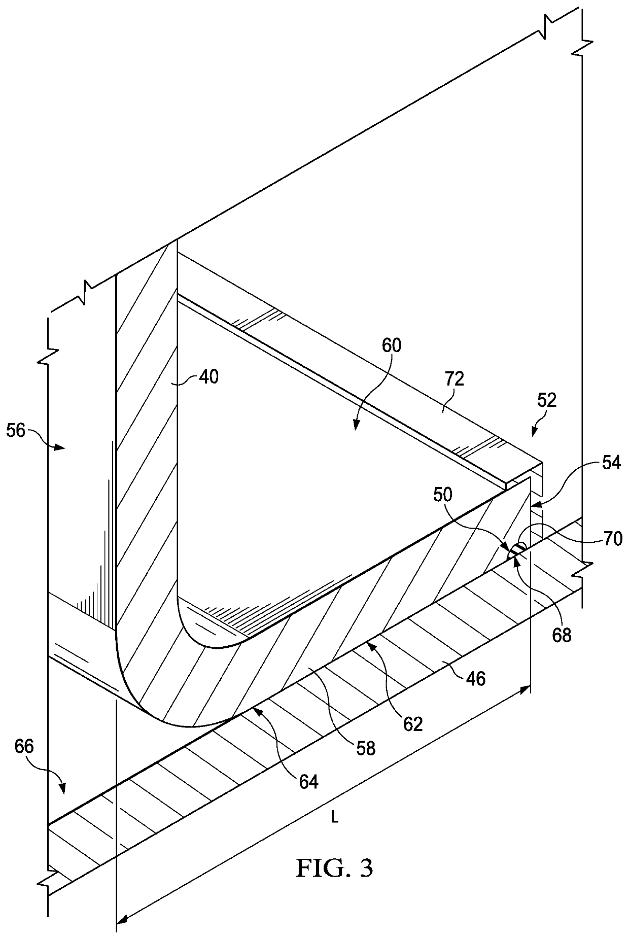
The edge seal arrangement has several advantages, such as simplifying the design of the seal, not requiring additional sealing operations after joining a part to a structure, and protecting components from corrosion and high-energy electrical discharges. It also forms an effective fluid seal against leakage. In wing box applications, the need for additional sealing and cleanup operations from within fuel tanks is eliminated.

Problems solved by technology

Carrying out these additional sealing operations within the confined space of the fuel tank is difficult and time-consuming.

Method used


Image

  • Part Edge Seal Arrangement and Joining Method
  • Part Edge Seal Arrangement and Joining Method
  • Part Edge Seal Arrangement and Joining Method

Examples


Embodiment Construction

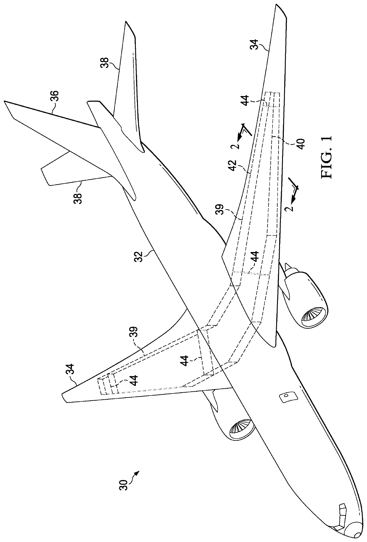
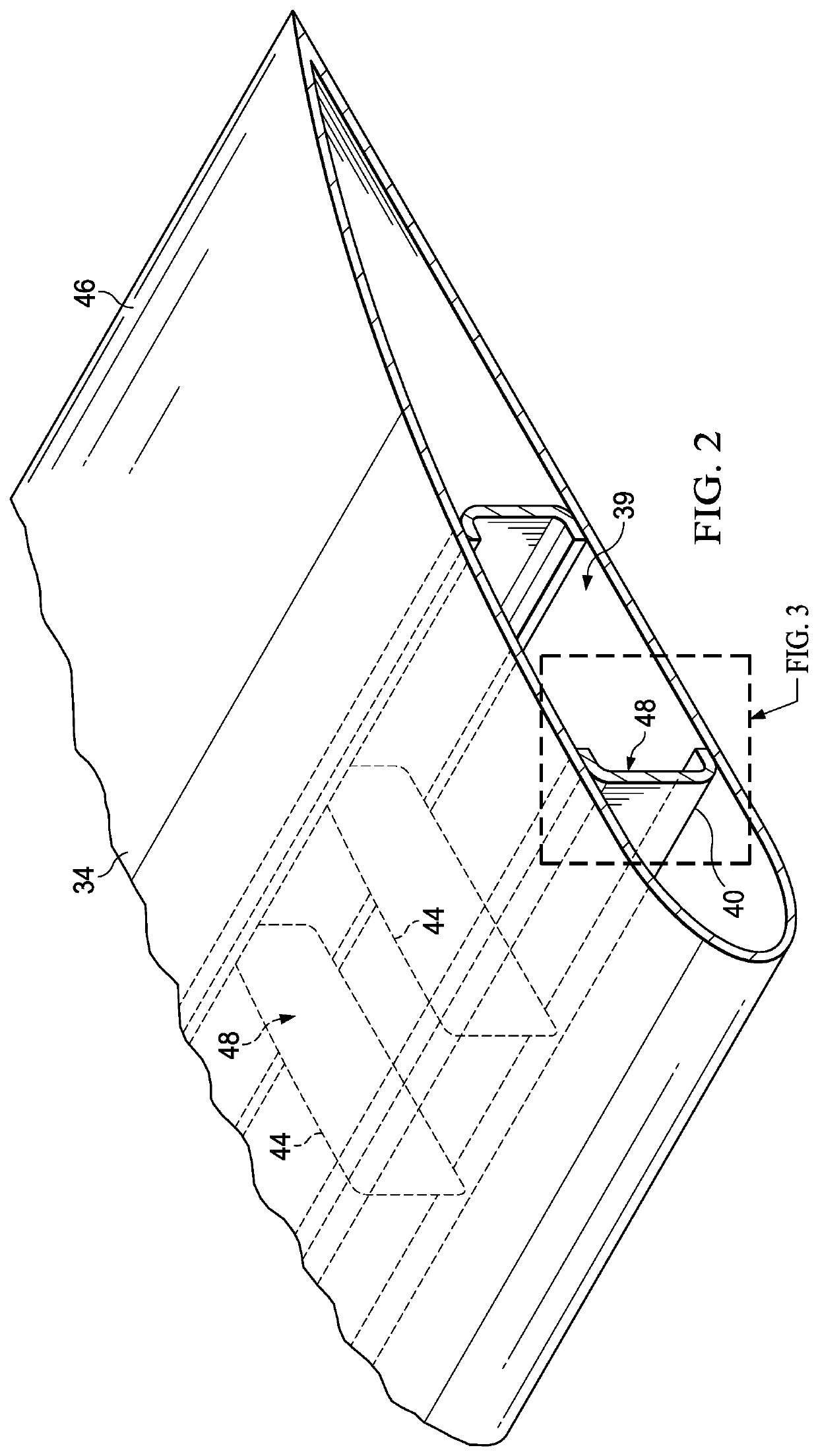
[0029]Referring first to FIG. 1, the disclosed embodiments provide an edge seal arrangement that may be used to seal and protectively cover exposed edges of composite laminate parts such as those employed in the construction of an airplane 30. The airplane 30 includes a fuselage 32, wings 34, a vertical stabilizer 36 and horizontal stabilizers 38. Each of the wings 34 includes a wing box 39 formed by forward and rear spars 40, 42 respectively, connected by longitudinally extending ribs 44. Wing skins 46 are joined to both the forward and aft spars 40, 42 as well as the ribs 44. In the disclosed embodiments, the forward and rear spars 40, 42, ribs 44 and wing skins 46 are formed of a fiber reinforced plastic laminate such as carbon fiber reinforced epoxy. Any of the structural members mentioned above are parts that may have one or more edges which have been cut to a desired size or length, thereby exposing the reinforcement fibers within the laminate at these edges.

[0030]Referring no...


PUM


Abstract

A seal arrangement is provided for sealing an exposed edge of a composite laminate part having a fay surface configured to be joined to a structure. The seal arrangement includes a precured edge seal covering the exposed edge and a cover covering the edge seal. A seal bead located within a recess in the fay surface of the part forms a seal between the part and the structure.

Description

BACKGROUND INFORMATION1. Field[0001]The present disclosure generally relates to treatments for part edges, and deals more particularly with a seal arrangement for a part edge, and a method of joining the part to a structure.2. Background[0002]It is sometimes desirable to seal an exposed edge of a part. For example, in the aircraft industry, structural members forming a wing box containing fuel tanks comprise carbon fiber reinforced polymer laminates. Some of these structural members may need to be cut to a desired size, resulting in cut edges in which the fibers are exposed. It is necessary to seal the cut edges in order to protect against fuel leakage, corrosion of adjacent metallic structures, and possible adverse effects of high-energy electrical charges such as those resulting from lightning strikes.[0003]Precured seals may be applied to the cut edges of wing box components such as spars before they are attached to wing skins. However, additional sealing operations are necessary...

Claims


Application Information

Patent Timeline
IPC IPC(8): F16J15/02B64F5/10
CPCF16J15/021B64F5/10B64D37/02B64C3/34
Inventor WU, STEVEN KUAN-CHISCHROEDER, IAN EDWARDSHADELL, MARK EDMONDUHLMAN, MELISSA A.WISEMAN, JESSE RANDALDANG, THO NGOCTANNER, RICHARD BRUCEMILLER, MELINDA DAETALCOTT, KRISTOPHER WILLIAM
Owner THE BOEING CO
Learn More