Defrost system

a technology of defrosting system and defrosting chamber, which is applied in the direction of defrosting, domestic cooling apparatus, application, etc., can solve the problem of reducing heat transfer efficiency

Inactive Publication Date: 2021-08-26
MAYEKAWA MFG CO LTD
View PDF8 Cites 1 Cited by
  • Summary
  • Abstract
  • Description
  • Claims
  • Application Information

AI Technical Summary

Benefits of technology

[0008]On the other hand, it is important to prevent icicles from forming in the lower part of the cooler by melting water flowing from the upper part of the cooler during defrosting.
[0011]With the defrost system configured as described above, the CO2 refrigerant liquid in the closed circuit drops by gravity to the first electric heater in the thermosiphon defrost circuit, and is heated and vaporized by the first electric heater. The vaporized CO2 refrigerant rises in the thermosiphon defrost circuit by the principle of thermosiphon, and the risen CO2 refrigerant gas heats the fin-tube heat exchanger provided inside the cooler, and heats and melts the frost attached to the outer surface of the fin-tube heat exchanger. The CO2 refrigerant that is liquefied by heating the fin-tube heat exchanger descends in the thermosiphon defrost circuit by gravity. The CO2 refrigerant liquid that has descended to the first electric heater is heated and vaporized again by the first electric heater. From the above, it is possible to preferably perform defrosting of a cooler and prevent icicles from being generated in a fin-tube heat exchanger at a lower part of a casing without having to install a warm brine circuit for heating a thermosiphon defrost circuit.

Problems solved by technology

During operation of the refrigeration apparatus, frost forms on the heat exchange tube provided in the cooler and reduces the heat transfer efficiency, and therefore it is necessary to perform defrosting (frost removal).

Method used


Image

  • Defrost system
  • Defrost system
  • Defrost system

Examples


Embodiment Construction

[0021]An embodiment of the present invention will be described with reference to FIGS. 1 to 6. Note that, in the description of the drawings, the same elements will be denoted by the same reference symbols, and redundant description will be omitted. The dimensional ratios in the drawings are exaggerated for the sake of convenience of description, and may differ from the actual ratios.

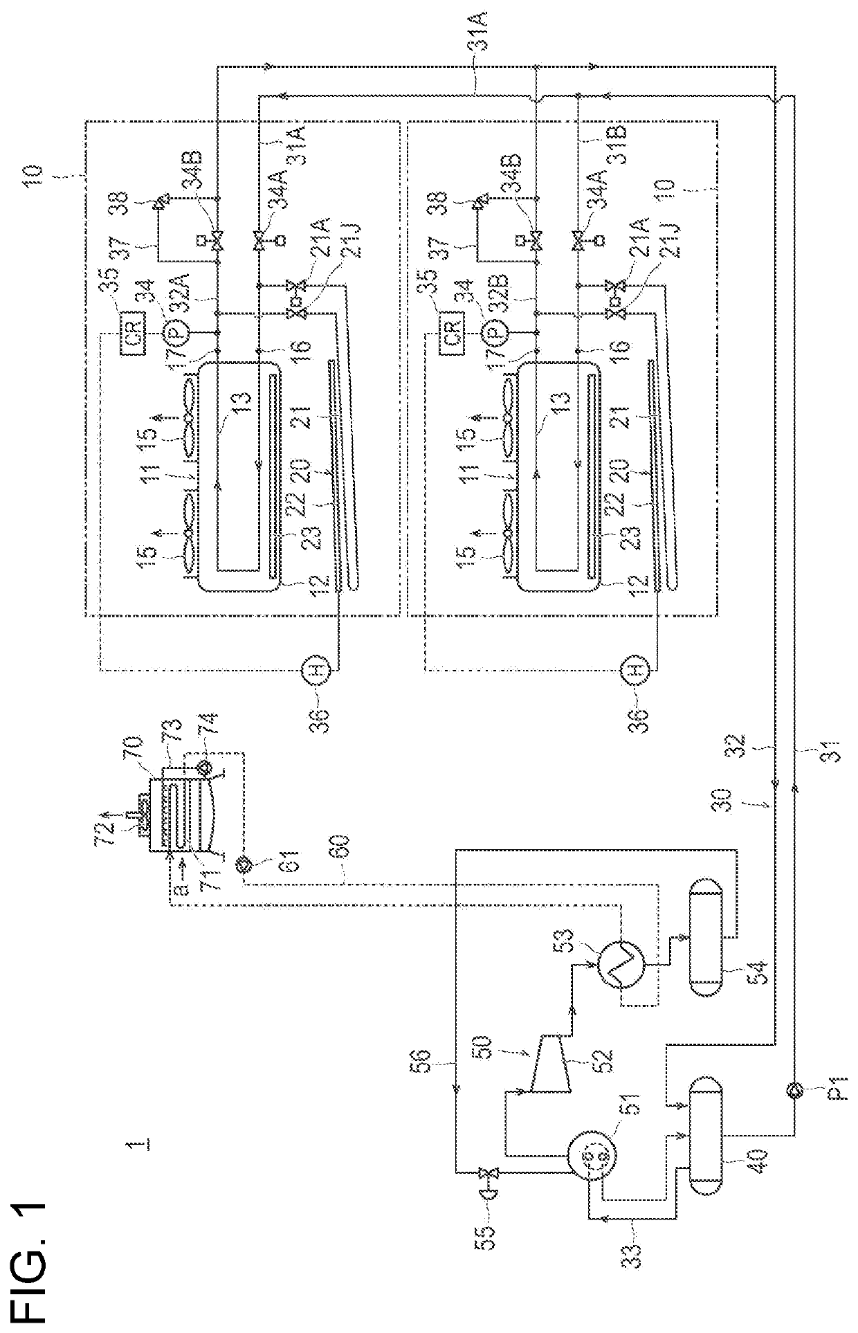
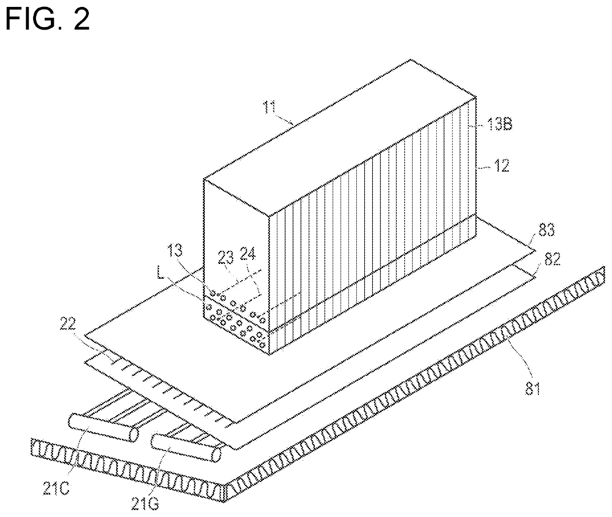
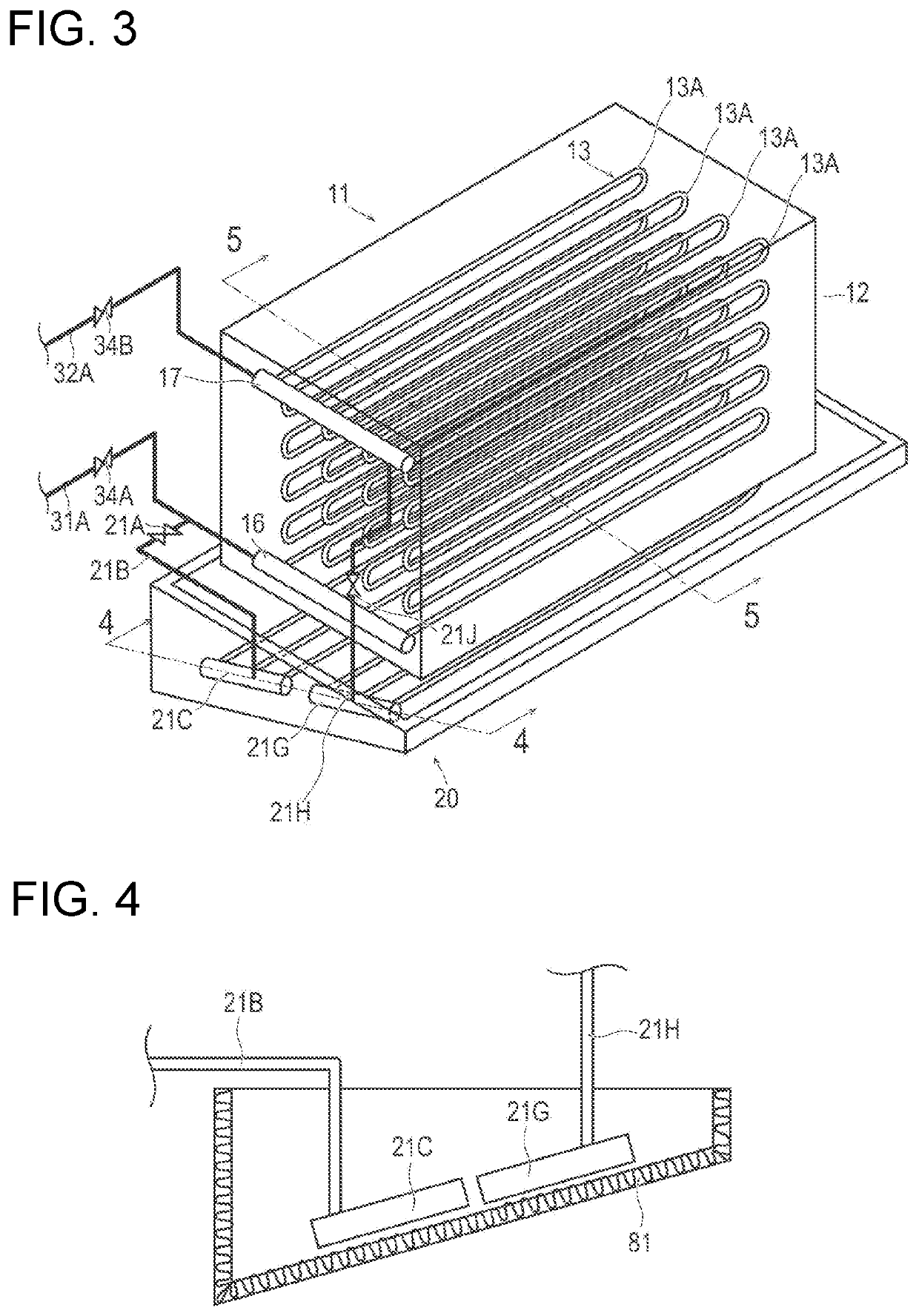
[0022]FIG. 1 is an overall configuration diagram of a refrigeration apparatus 1 according to the present embodiment. FIG. 2 is a schematic perspective view of a cooler 11, a defrost system 20, and the like according to the present embodiment. FIG. 3 is a schematic diagram of the cooler 11 and the defrost system 20 according to the present embodiment. FIG. 4 is a sectional view taken along line 4-4 in FIG. 3. FIG. 5 is a sectional view taken along line 5-5 in FIG. 3. FIG. 6 is a schematic diagram showing a thermosiphon defrost circuit 21 according to the present embodiment.

[0023]As shown in FIG. 1, a ref...


PUM


Abstract

To provide a defrost system capable of preferable defrosting and prevention of generation of icicles on a casing without installing a brine circuit. A defrost system includes a thermosiphon defrost circuit that is provided by being branched from a circulation line, in which, at the time of defrosting, a CO2 refrigerant staying inside a fin-tube heat exchanger repeats a two-phase change of a gaseous form and reliquefaction, and which forms a CO2 circulation path together with the fin-tube heat exchanger; electromagnetic opening / closing valves and that are closed at the time of defrosting and set the CO2 circulation path to a closed circuit; and a first electric heater arranged above the thermosiphon defrost circuit so as to be adjacent to the thermosiphon defrost circuit, and naturally circulates the CO2 refrigerant in the closed circuit at the time of defrosting.

Description

TECHNICAL FIELD[0001]The present invention relates to a defrost system applied to a refrigeration apparatus that cools the interior of a cold storage room by circulating a CO2 refrigerant in a cooler provided in the cold storage room, and for removing frost attached to a fin-tube heat exchanger provided in the cooler.BACKGROUND ART[0002]From the viewpoint of preventing ozone layer depletion, preventing global warming, and the like, a refrigeration apparatus in which, as a refrigerant of a refrigeration apparatus used for indoor air conditioning, refrigeration of food, and the like, ammonia that has high cooling performance but is toxic is used as a primary refrigerant and CO2 that is non-toxic and odorless is used as a secondary refrigerant has widely been used.[0003]In such a refrigeration apparatus, a primary refrigerant circuit in which ammonia refrigerant circulates and a secondary refrigerant circuit in which CO2 refrigerant circulates are connected by a cascade condenser, and ...

Claims


Application Information

Patent Timeline
Patent Type & Authority Applications(United States)
IPC IPC(8): F25D21/08F25D21/00
CPCF25D21/08F25D21/002F25B41/00F25B47/02F25B41/20F25B2309/06F25D17/02F25B25/005F25B15/04F25B41/40F25B2700/19F25B2600/2525F25B2400/01
Inventor YOSHIKAWA, CHOIKUKUTSUNA, TOSHIOMUGABI, NELSONKAYASHIMA, DAIKIOOSUGA, NOBUO
Owner MAYEKAWA MFG CO LTD
Why Eureka
Try Eureka