
Computer-implemented method for simulating an electrical circuit

a computer and circuit technology, applied in computing, instruments, electric digital data processing, etc., can solve the problems of high cost of procedure, speed advantage, and difficulty in certain numerical operations such as division

Pending Publication Date: 2021-08-26
DSPACE DIGITAL SIGNAL PROCESSING & CONTROL ENG
View PDF0 Cites 0 Cited by
  • Summary
  • Abstract
  • Description
  • Claims
  • Application Information

AI Technical Summary

Benefits of technology

The patent describes a method for simulating the operation of an electrical circuit using time-discrete circuit equations. This allows for a more efficient and accurate simulation of the circuit, without the need for multiple mathematical representations. It also introduces a technique for feed-forward control to improve the speed at which switch elements change state. This helps to minimize the time it takes for the circuit to transition between different states. The technical effect of this patent is to simplify the simulation of complex electrical circuits and save memory space.

Problems solved by technology

It is also possible that one computing unit or a plurality of computing units is or are implemented based on one (or more) FPGA (field programmable gate array), which results in speed advantages but also difficulties with regard to certain numerical operations such as division.
The particular difficulty with electrical circuits including switch elements consists in that these switch elements cannot be represented as terms of an equation as such, but a change in the switched state of a switch element always leads to a change in the structure of the circuit under consideration and thus also to a modified mathematical representation.
It can easily be recognized that this procedure is very expensive.

Method used


Image

  • Computer-implemented method for simulating an electrical circuit
  • Computer-implemented method for simulating an electrical circuit
  • Computer-implemented method for simulating an electrical circuit

Examples


Embodiment Construction

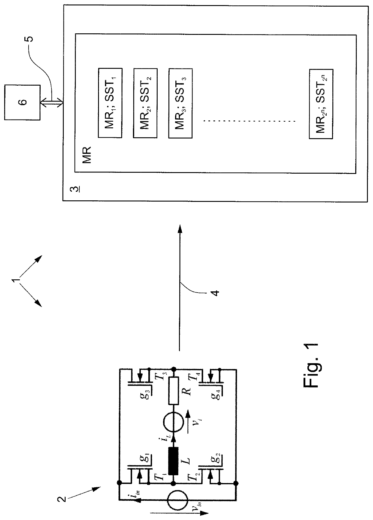
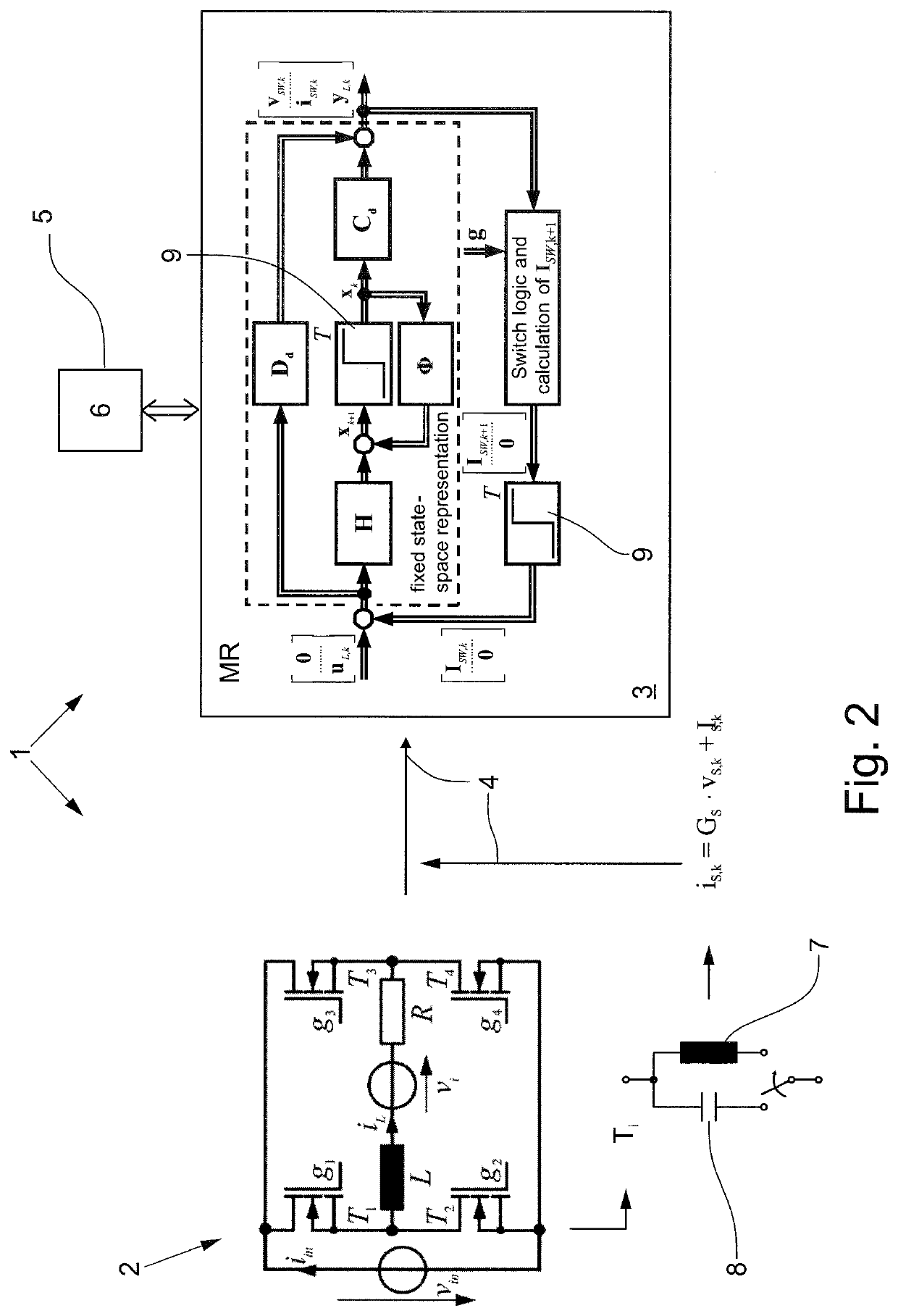
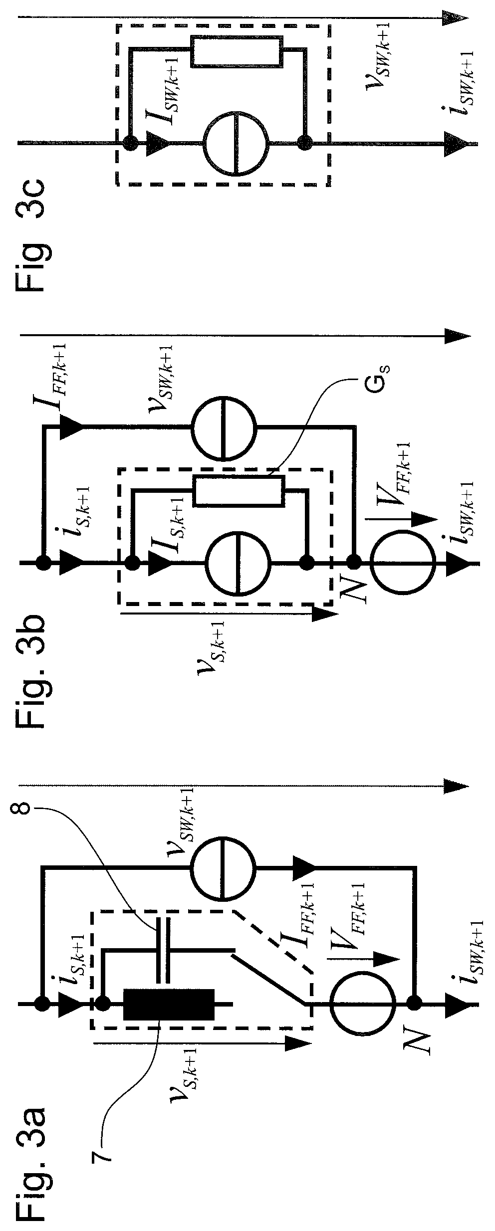
[0031]FIGS. 1 to 5 show a computer-implemented method 1 with different priorities for simulating an electric circuit 2 with circuit components R, L, T.

[0032]FIG. 1 shows such a computer-implemented method 1 for simulating an electrical circuit 2 via at least one computing unit 3, as is known from the conventional art. The circuit 2 in FIG. 1 is a simple single-phase full bridge inverter. The electric circuit 2 includes various circuit components R, L, T, for example, a coil L, an ohmic resistor R and MOSFET transistors T1, T2, T3, T4 with control terminals g1, g2, g3, g4. Here, the MOSFET transistors T1, T2, T3, T4 represent the switch elements Ti. These switch elements Ti can either assume a conductive or a blocking switched state.

[0033]Subsequently, the electrical circuit 2 is described 4 by a mathematical representation MR. Depending on the individual switched state of the respective switch element Ti, different total switched states SSTi occur in the circuit 2. By numerically so...


PUM


Abstract

A computer-implemented method for simulating an electrical circuit via at least one computing unit, the electrical circuit comprising circuit components with switch elements, wherein the switch elements are capable of assuming either a conductive or a blocking switched state, wherein the circuit is described by a mathematical representation MR and the circuit for each total switched state is calculated on the computing unit by numerically solving the mathematical representation MR describing the total switched state.

Description

[0001]This nonprovisional application is a continuation of International Application No. PCT / 2019 / 081535, which was filed on Nov. 15, 2019, and which claims priority to German Patent Application No. 10 2018 128 653.8, which was filed in Germany on Nov. 15, 2018, and which are both herein incorporated by reference.BACKGROUND OF THE INVENTIONField of the Invention[0002]The present invention relates to a computer-implemented method for simulating an electrical circuit via at least one computing unit, wherein the electrical circuit comprises circuit components having switch elements, the switch elements being capable of assuming either a conductive or a blocking switched state, the circuit being described by a mathematical representation and the circuit for each total switched state being calculated on the computing unit by numerically solving the mathematical representation describing the total switched state.Description of the Background Art[0003]The invention is related to the techni...

Claims


Application Information

Patent Timeline
Patent Type & Authority Applications(United States)
IPC IPC(8): G06F30/3308G06F30/337
CPCG06F30/3308G06F30/337G06F30/367G06F30/33
Inventor KIFFE, AXELWITTING, KATRIN
Owner DSPACE DIGITAL SIGNAL PROCESSING & CONTROL ENG
Learn More