Low resistance cage for pulse jet filter

a filter and low resistance technology, applied in the field of industrial pulse jet filters, can solve the problems of reducing the resistance of the gas flow path, limiting the process gas flow, and the overall length of the filter cage, so as to reduce the resistance to the gas flow path and increase the internal volume of the bag

Pending Publication Date: 2021-09-02
ALL FILTRATION TECH (HLDG) PTY LTD
View PDF15 Cites 3 Cited by
  • Summary
  • Abstract
  • Description
  • Claims
  • Application Information

AI Technical Summary

Benefits of technology

[0012]In a first aspect, the present invention relates to a cage for a tubular, extended surface filter bag that increases the internal volume of the bag and provides reduced resistance to the gas flow path through the cage.
[0015]Preferably, the cage supports are in the form of pressed metal straps having a wide body extending between two thin edges. When the cage supports are joined to the vertical cage wires, the two thin edges are orientated in the direction of the gas flow path through the cage thereby providing the reduced resistance to the gas flow path.
[0017]In a preferred embodiment, the present invention relates to a cage for a tubular, extended surface filter bag, comprising:a plurality of vertical cage wires extending longitudinally;at least one horizontal cage support shaped to support the vertical cage wires in a tubular formation; andwherein the at least one horizontal cage support has a minimal surface area orientated longitudinally to the vertical cage wires, thereby maximizing gas flow inside the extended surface filter bag, and providing reduced resistance of the horizontal cage support.

Problems solved by technology

However, a primary limitation in extended-surface filter bags is the overall ‘length’ of the filter cage.
These non-circular horizontal supports increase the resistance of the cage itself compared with a conventional round filter bag cage, which has the potential to restrict both process gas flow during filtration and reverse pulse air during filter cleaning.
However, in use, there were mechanical limitations with the wire spider.
However, all known pressed metal spiders present considerable surface area to the lengthwise (or longitudinal) air flow inside the filter bag and the resulting drag detracts from filter efficiency.
However, the pressed metal spiders as suggested are prone to aerodynamic drag.

Method used


Image

  • Low resistance cage for pulse jet filter
  • Low resistance cage for pulse jet filter
  • Low resistance cage for pulse jet filter

Examples


Embodiment Construction

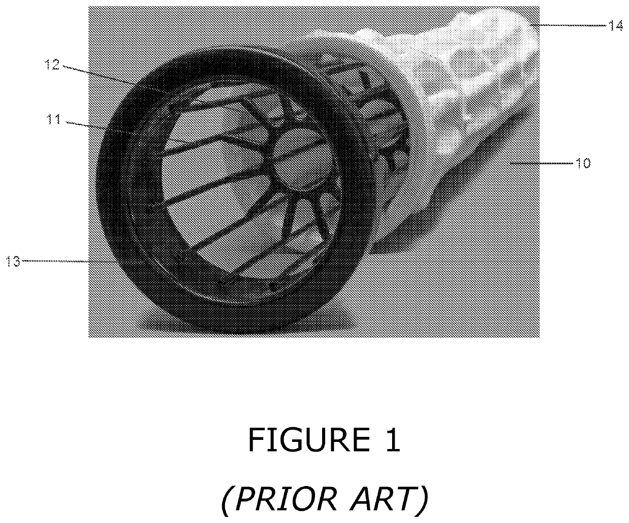
[0035]As shown in FIG. 1, a prior art wire cage 10 for a pulse-jet filter includes a cylindrical array of longitudinal and normally vertical cage wires 11. In this example of the prior art, the cage supports 12 are in the form of spaced apart pressed metal spiders. Typically, the supports are welded to each of the cage wires. The wire cage has an inlet 13 at one end and a terminal end or floor 14 at the other end. The cage supports are internal, that is, welded to the interior surface of each of the cage wires.

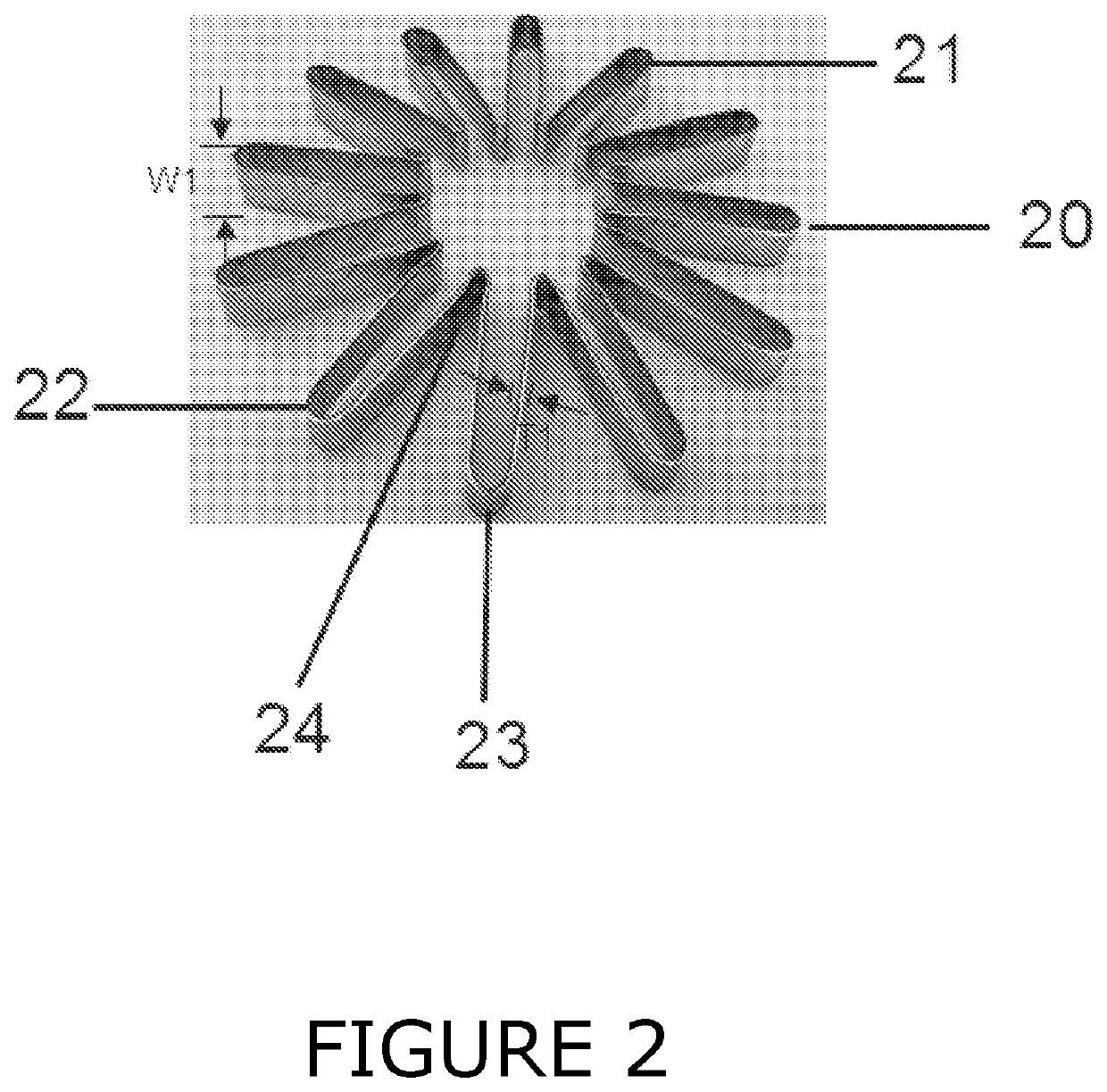
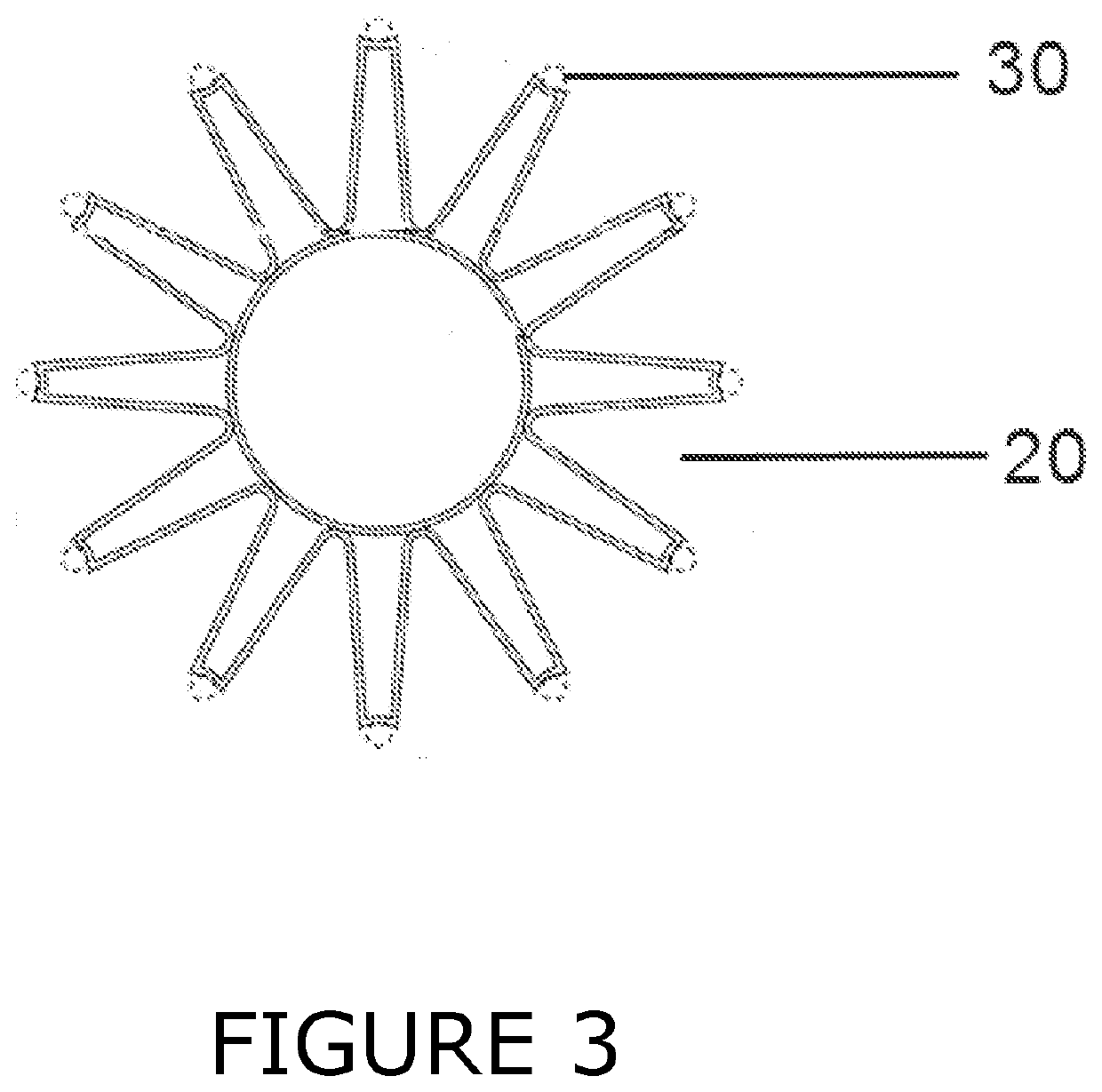
[0036]As suggested by FIGS. 2-5, the technology of the present invention provides a novel spider or cage support 20 for an extended surface filter bag. The support 20 is formed from a thin metal sheet, which provides a much lower cross-sectional area with respect to the gas flow paths (which run in a direction that is longitudinal to the length the cage), but even with this reduced cross-sectional area, still provides structural integrity to the cage.

[0037]The support 20 is in...


PUM

PropertyMeasurementUnit
thicknessaaaaaaaaaa
thicknessaaaaaaaaaa
widthaaaaaaaaaa

Abstract

The present invention relates to a cage for a tubular, extended surface filter bag that increases the internal volume of the bag and provides reduced resistance to the gas flow path through the cage. The cage includes a plurality of vertical cage wires that extend longitudinally, and has at least one horizontal cage support shaped to support the vertical cage wires in a tubular formation. The cage supports are in the form of pressed metal straps having a wide body extending between two thin edges.

Description

PRIORITY DETAILS[0001]The present application claims priority from Australian provisional patent application 2018902484, filed on 9 Jul. 2018, the entirety of which is incorporated herein by reference.TECHNOLOGY FIELD[0002]The invention relates to industrial pulse jet filters and more particularly to improvements to the wire frame or cage for an extended surface filter bag.[0003]Most particularly, the present invention relates to cage supports that are formed from a thin metal sheet, and have a lower cross-sectional area with respect to the gas flow paths through the wire cage.BACKGROUND[0004]In industrial gas filtration, pulse-jet filters are tubular filter bags, mounted onto wire cages and mounted into bag-houses containing multiple filters. Dust-laden gas is drawn through the filter bags during the filtering process and particulate material is captured on the outer surface of the filter bag. These filter bags are closed on the bottom and open on the top where the cleaned gas exit...

Claims


Application Information

Patent Timeline
Patent Type & Authority Applications(United States)
IPC IPC(8): B01D46/08B01D46/00
CPCB01D46/08B01D2265/06B01D46/0068B01D46/24B01D2201/04B01D2201/0415B01D2275/201B01D46/71B01D46/06
Inventor CURRELL, BRADLEY MICHAELNEATE, MICHAEL JAMES
Owner ALL FILTRATION TECH (HLDG) PTY LTD
Why Eureka
Try Eureka