
Ratchet wrench

Inactive Publication Date: 2021-09-02
WANG JEN YU
View PDF0 Cites 0 Cited by
  • Summary
  • Abstract
  • Description
  • Claims
  • Application Information

AI Technical Summary

Benefits of technology

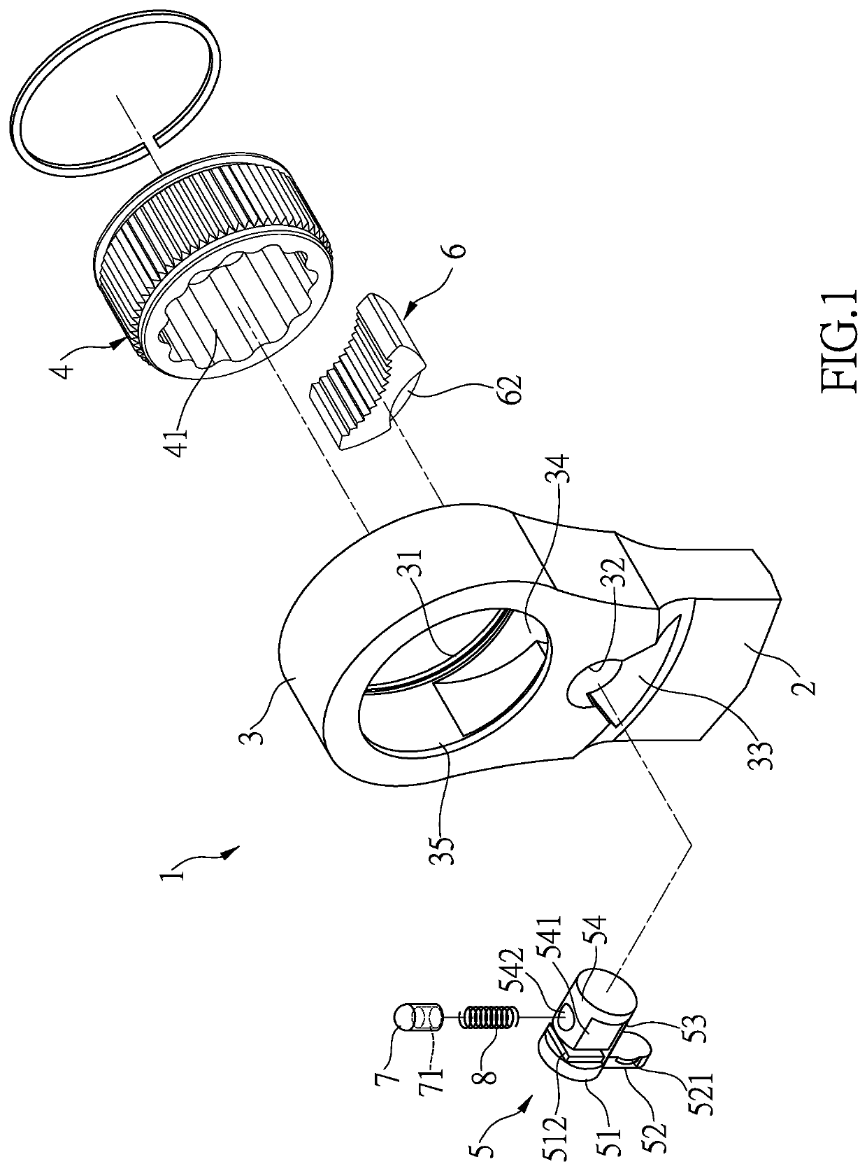
The present invention is a ratchet wrench that includes a handle and a head with a through hole having two openings. The through hole has a recess on its inner periphery and a circular hole through the neck of the head that communicates with the recess. A ratchet wheel is rotatably received in the through hole and located corresponding to the two openings. A switch member is inserted into the circular hole and located in the recess. The switch member has a head end, a tail end, and a connection portion between them. A lever extends from the head end. A gap is formed between the connection portion and the inside of the recess to accommodate a pawl that is movable in the recess. The pawl has a toothed front face and a curved-recessed back located opposite the toothed front face and is located between the ratchet wheel and the switch member. A flange extends from the curved-recessed back and restricts the switch member from dropping. A tubular member has a first end contacting the curved-recessed back, and a spring is biased between the second end of the tubular member and the extension portion.

Problems solved by technology

However, the strong springs make the switch member difficult to be operated.
Besides, the switch member does not have a proper mechanism to avoid it from dropping out from the head of the wrench

Method used


Image

  • Ratchet wrench
  • Ratchet wrench
  • Ratchet wrench

Examples


Embodiment Construction

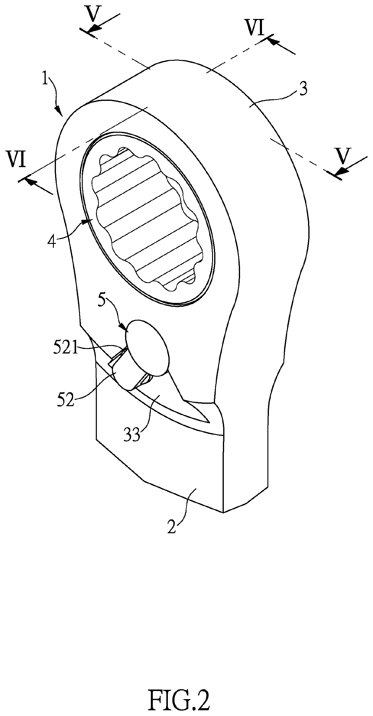
[0017]Referring to FIGS. 1 to 6, the ratchet wrench 1 of the present invention comprises a handle 2 and a head 3 which is formed to one end of the handle 2. The head 3 includes a through hole which forms a first opening 31 and a second opening 35 in two opposite sides of the head 3. A recess 34 is defined in the inner periphery of the through hole, and a circular hole 32 is defined through the neck of the head 3 and communicates with the recess 34.

[0018]A ratchet wheel 4 is rotatably received in the through hole of the head 3 and located corresponding to the first and second openings 31, 35. A C-clip is used to position the ratchet wheel 4 in the head 3 and prevents the ratchet wheel 4 from dropping from the first opening 31. The ratchet wheel 4 includes a mounting hole 41.

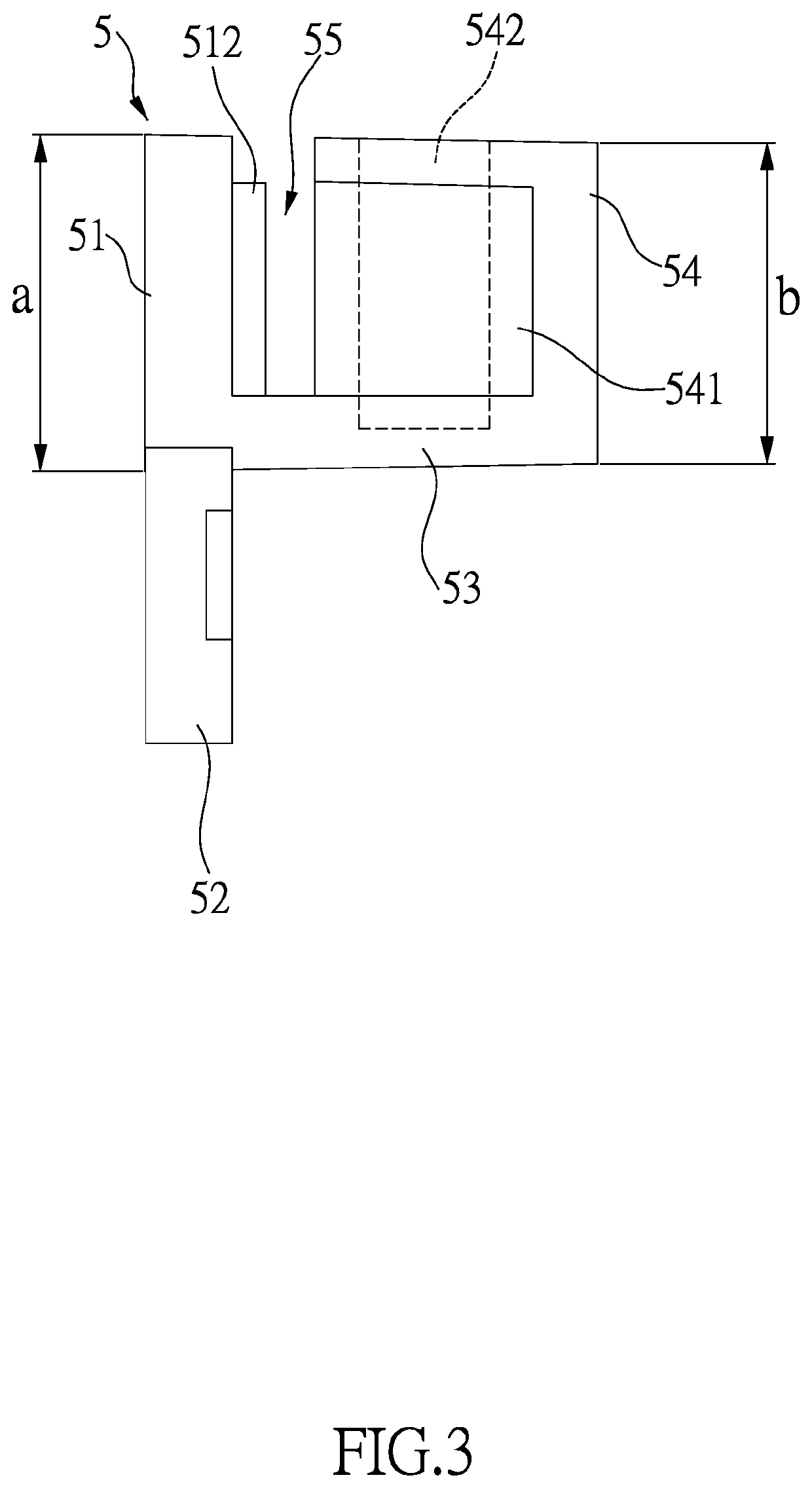
[0019]A switch member 5 includes a head end 51, a tail end 54 and a connection portion 53 that is formed between the head end 51 and the tail end 54. A lever 52 extends perpendicularly from the head end 51. The ta...


PUM


Abstract

A ratchet wrench includes a through hole defined through the head of the wrench and a recess is defined in the inner periphery of the through hole. A circular hole is defined through the head and communicates with the recess. A ratchet wheel is rotatably received in the through hole of the head. A pawl is movably located in the recess and engaged with the ratchet wheel. A switch member is rotatable inserted into the circular hole and has a lever located outside of the head of the wrench. A slot is defined transversely in the switch member. The slot is located corresponding to the recess. The switch member receives one end of a spring which biases a tubular member contact the pawl. The pawl has a flange which is located in the slot such that the switch member does not drop from the circular hole.

Description

BACKGROUND OF THE INVENTION1. Fields of the Invention[0001]The present invention relates to a ratchet wrench, and more particularly, to a switch member of a ratchet wrench.2. Descriptions of Related Art[0002]The conventional ratchet wrench as disclosed in Taiwanese Patent No. I 670147, which discloses a switch member that is able to be pivoted to change the ratcheting direction of the ratchet wrench. The switch member includes an insertion portion inserted into the head of the wrench, and the insertion portion is located between two pawls. Each pawl is biased by a spring to clamp the insertion portion between the two pawls. The spring force of each spring has to be strong enough to avoid the switch member from being pivoted by impact or the like. However, the strong springs make the switch member difficult to be operated. Besides, the switch member does not have a proper mechanism to avoid it from dropping out from the head of the wrench[0003]The present invention intends to provide...

Claims


Application Information

Patent Timeline
IPC IPC(8): B25B13/46B25B23/00
CPCB25B13/463B25B23/0007
Inventor WANG, JEN-YU
Owner WANG JEN YU
Learn More