Display device and surface light source

a technology of light source and display device, which is applied in the direction of instruments, non-linear optics, optics, etc., can solve the problem achieve the effect of reducing light transmission

Active Publication Date: 2021-09-02
FUNAI ELECTRIC CO LTD
View PDF0 Cites 0 Cited by
  • Summary
  • Abstract
  • Description
  • Claims
  • Application Information

AI Technical Summary

Benefits of technology

[0005]In the case where an optical member is in the form of a sheet, as in Patent Literature 1 above, the optical member tends to deflect, and therefore a plurality of support members need to be arranged. However, if there are many support members in place, the light path can be blocked by the support members, which reduces the light transmission.
[0006]It has been discovered, in order to reduce the number of the support members and suppress the deflection of the optical member, to apply an adhesive to the entire surface of the optical member or the diffusion plate and integrate the diffusion plate and the optical member by overlapping and bonding the optical member to the diffusion plate. However, with this configuration, because the adhesive has a greater refractive index than the air, the light can be refracted at the interface between the adhesive and the air. As a result, the refraction can change the direction of the path of the light and the light diffusion range can become narrower than that of the air layer, which can reduce the diffusion effect of the optical member that is provided for making the luminance distribution of the irradiated light uniform.
[0007]One object is to provide a display device and a surface light source device that can suppress deflection of an optical member and improve the diffusion effect of light while reducing the number of support members.

Problems solved by technology

However, if there are many support members in place, the light path can be blocked by the support members, which reduces the light transmission.

Method used


Image

  • Display device and surface light source
  • Display device and surface light source
  • Display device and surface light source

Examples


first embodiment

Effect of First Embodiment

[0056]In the first embodiment, the following effects can be achieved.

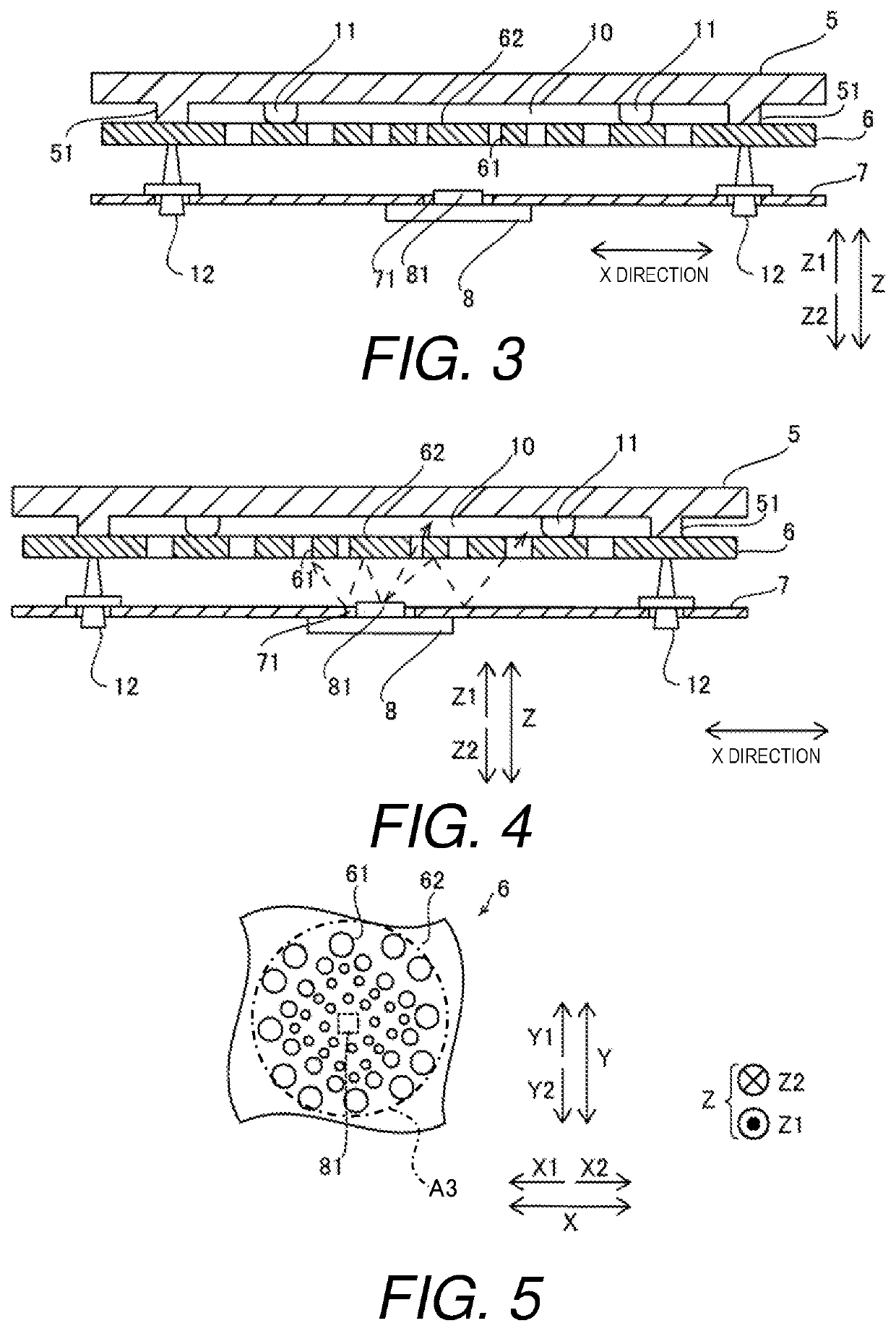
[0057]In the first embodiment, as described above, the liquid crystal television device 100 comprises the adhesive layers 11 bonding the optical member 6 and the diffusion plate 5 with the air layer 10 therebetween. The adhesive layers 11 are arranged spaced apart from each other in the direction in which the optical member 6 extends. The air layer 10 has the same thickness as the adhesive layers 11 and is located between the adjacent pairs of the adhesive layers 11. With this configuration, the optical member 6 is supported by the diffusion plate 5 by bonding the optical member 6 and the diffusion plate 5 via the adhesive layers 11. Thus, the optical member 6 can be prevented from deflecting even if a large number of support members 12 are not arranged. The adhesive layers 11 are arranged spaced apart from each other in the direction in which the optical member 6 extends, and the air laye...

second embodiment

Effect of Second Embodiment

[0072]In the second embodiment, as in the first embodiment above, the liquid crystal television device 200 comprises the adhesive layers 11 bonding the optical member 6 and the diffusion plate 5 with the air layer 10 therebetween. The adhesive layers 11 are arranged spaced apart from each other in the direction in which the optical member 6 extends. The air layer 10 has the same thickness as the adhesive layers 11 and is located between the adjacent pairs of the adhesive layers 11. With this configuration, the optical member 6 is supported by the diffusion plate 5 by bonding the optical member 6 and the diffusion plate 5 via the adhesive layers 11. Thus, the optical member 6 can be prevented from deflecting even if a large number of support members 12 are not arranged. The adhesive layers 11 are arranged spaced apart from each other in the direction in which the optical member 6 extends, and the air layer 10 between the optical member 6 and the diffusion p...

third embodiment

Effect of Third Embodiment

[0079]In the third embodiment, as in the first embodiment above, the liquid crystal television device 300 comprises the adhesive layers 11 bonding the optical member 6 and the diffusion plate 5 with the air layer 10 therebetween. The adhesive layers 11 are arranged spaced apart from each other in the direction in which the optical member 6 extends. The air layer 10 has the same thickness as the adhesive layers 11 and is located between the adjacent pairs of the adhesive layers 11. With this configuration, the optical member 6 is supported by the diffusion plate 5 by bonding the optical member 6 and the diffusion plate 5 via the adhesive layers 11. Thus, the optical member 6 can be prevented from deflecting even if a large number of support members 12 are not arranged. The adhesive layers 11 are arranged spaced apart from each other in the direction in which the optical member 6 extends, and the air layer 10 between the optical member 6 and the diffusion pla...


PUM

PropertyMeasurementUnit
thicknessaaaaaaaaaa
thicknessaaaaaaaaaa
thicknessaaaaaaaaaa

Abstract

A display device includes a display panel, at least one light source, a diffusion plate, an optical member, and a plurality of adhesive layers. The diffusion plate diffuses light from the at least one light source. The optical member is disposed between the diffusion plate and the at least one light source and has at least one transmitting portion that transmits the light from the at least one light source and a reflective portion that reflects the light from the at least one light source. The adhesive layers bond the optical member and the diffusion plate with an air layer therebetween. The adhesive layers are arranged spaced apart from each other in a direction in which the optical member extends. The air layer has the same thickness as the adhesive layers and is located between an adjacent pair of the adhesive layers.

Description

CROSS-REFERENCE TO RELATED APPLICATIONS[0001]This application claims priority to Japanese Patent Application No. 2020-034964 filed on Mar. 2, 2020. The entire disclosure of Japanese Patent Application No. 2020-034964 is hereby incorporated herein by reference.BACKGROUNDField of the Invention[0002]This invention generally relates to a display device and a surface light source device. More specifically, the present invention relates to a display device and a surface light source device equipped with an optical member and a diffusion plate.Background Information[0003]Generally, a display device is equipped with an optical member and a diffusion plate (see International Publication No. WO 2017 / 038082 (Patent Literature 1), for example).[0004]Patent Literature 1 above discloses a display device including a light source substrate with a plurality of light sources, an optical member, a support member, and a diffusion plate. The light sources emit light. The optical member homogenizes a lum...

Claims


Application Information

Patent Timeline
Patent Type & Authority Applications(United States)
IPC IPC(8): G02F1/13357
CPCG02F1/133606G02F1/133608G02F1/133605G02F1/133602G02F1/133603G02F1/133611G02F2202/28
Inventor KOBAYASHI, TOMOHIRO
Owner FUNAI ELECTRIC CO LTD
Why Eureka
Try Eureka