
Control assembly of a solenoid valve, solenoid valve assembly and associated methods

a technology of solenoid valve and assembly, which is applied in the direction of valve operating means/release devices, mechanical equipment, applications, etc., can solve the problems of reducing the performance and/or malfunctioning and breakage reducing the performance of the solenoid valve and the times of its use,

Active Publication Date: 2021-09-09
RPE
View PDF0 Cites 3 Cited by
  • Summary
  • Abstract
  • Description
  • Claims
  • Application Information

AI Technical Summary

Benefits of technology

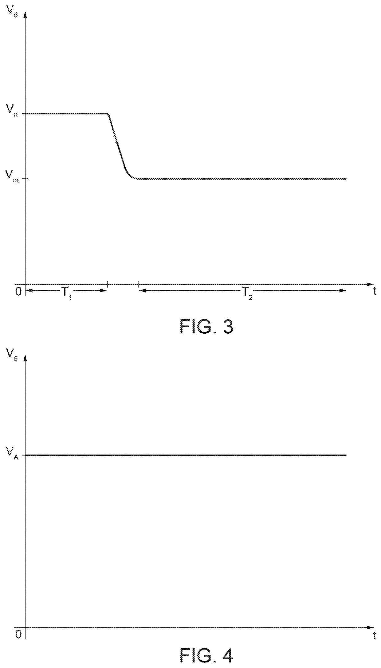
The present invention provides a control assembly for a solenoid valve that reduces overheating, improves performance, and reduces consumption. The control assembly includes a control device and a control assembly with a lower hold voltage and current for the second period of time. The method also includes interposing a control assembly between the control device and the solenoid valve to increase the performance of a delivery device. This results in better performance of the solenoid valve due to reduced overheating, which allows it to operate for longer periods of time and under greater pressure.

Problems solved by technology

One drawback of the prior art is that the solenoid valve can overheat in use, in particular during prolonged periods of use, causing a reduction in performance and / or malfunctioning and breakage.
This problem is mostly encountered when the solenoid valve is used to regulate a flow of vapor or hot fluids and / or in hot environments.
Generally, to limit the overheating of the solenoid valve, the maximum time of using the solenoid valve is limited in each operating cycle, however, the drawback is that it reduces the performance of the solenoid valve and the times of its use.

Method used


Image

  • Control assembly of a solenoid valve, solenoid valve assembly and associated methods
  • Control assembly of a solenoid valve, solenoid valve assembly and associated methods
  • Control assembly of a solenoid valve, solenoid valve assembly and associated methods

Examples


Embodiment Construction

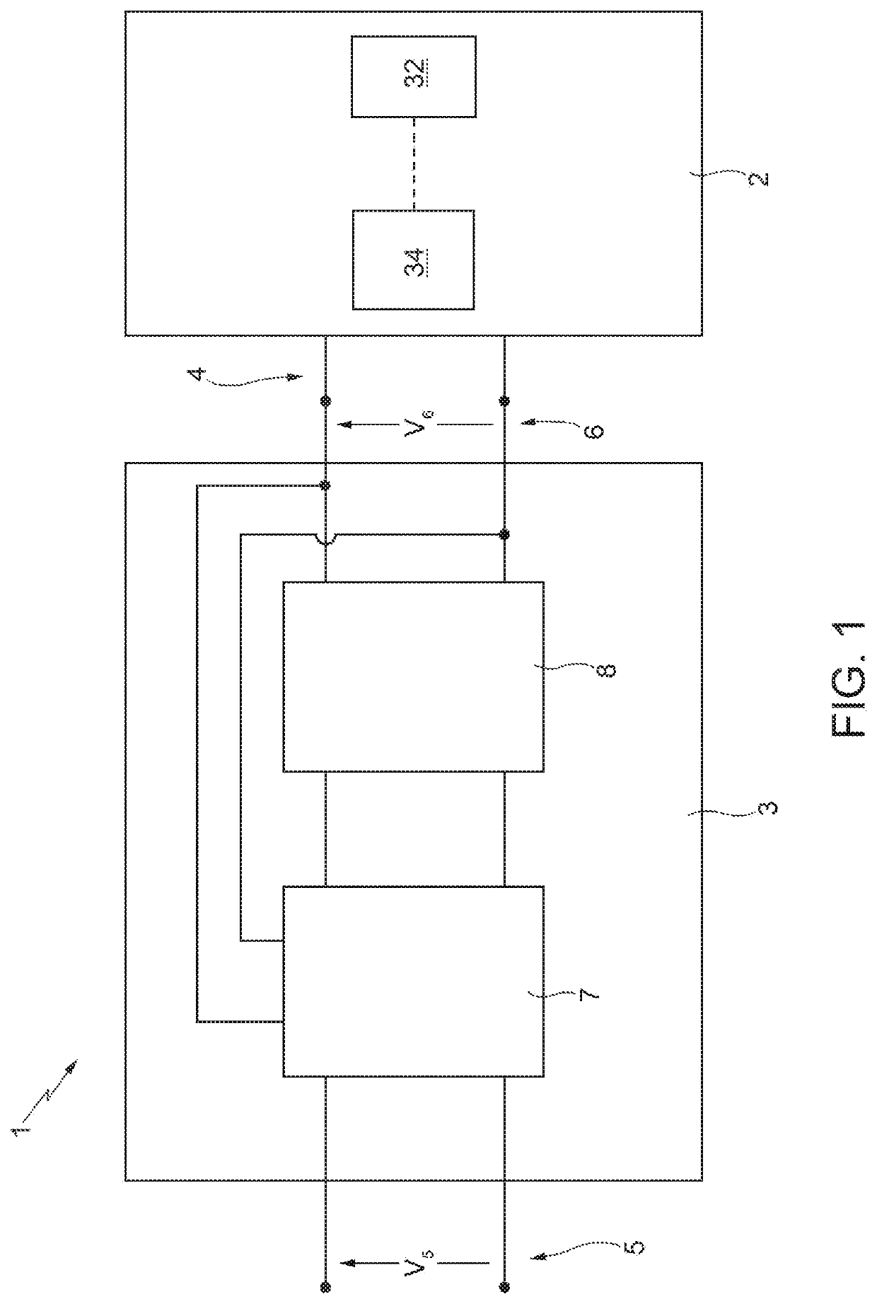
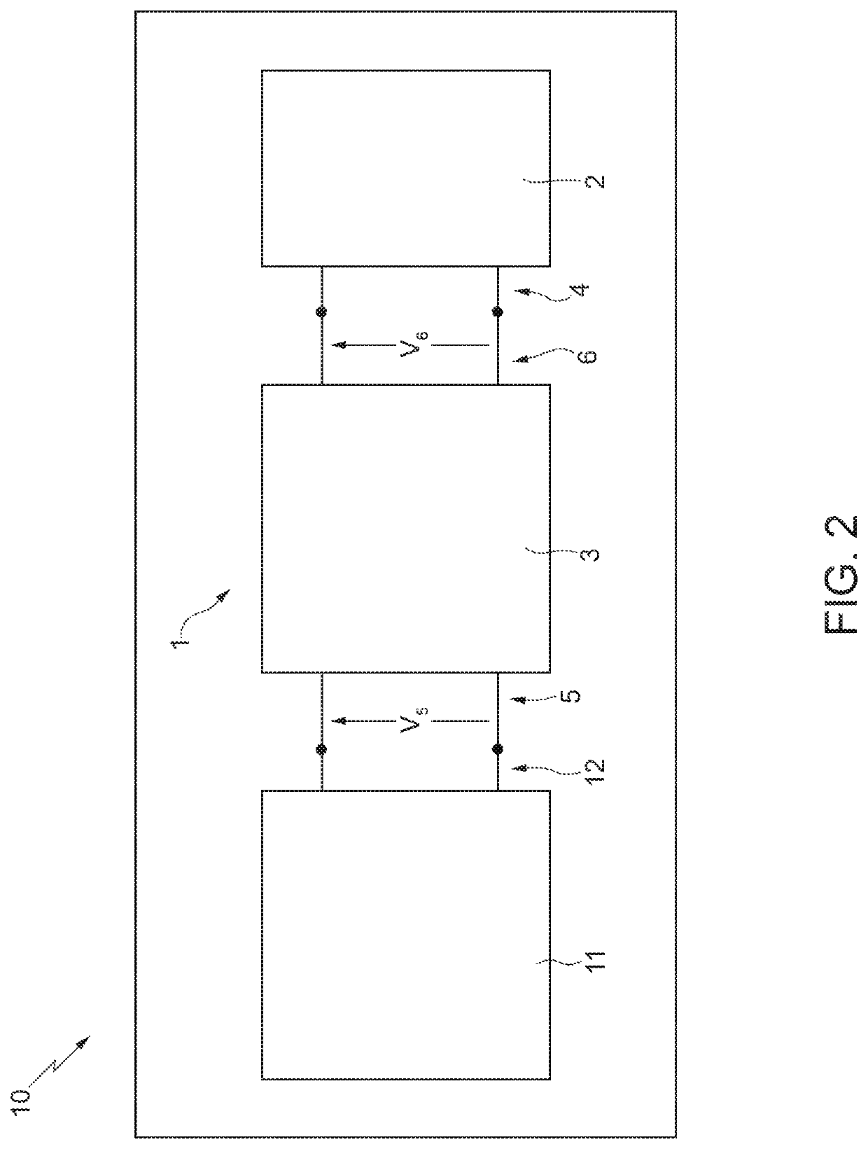
[0035]With reference to FIG. 1, 1 globally defines a solenoid assembly for a fluid delivery device 10 (FIG. 2). The solenoid assembly 1 comprises a monostable solenoid valve 2 and a control assembly 3 of the monostable solenoid valve 2.

[0036]The monostable solenoid valve 2 comprises a power supply input 4 for receiving voltage and electric current. In greater detail, the monostable type solenoid valve 2 requires a power supply for being opened or closed depending on whether it is of a normally closed type or a normally open type, and it requires a power supply for the whole time the solenoid valve is to be kept open or closed. When the monostable type solenoid valve 2 is no longer supplied, it returns to its original open or closed position by itself, depending on whether it is of the type that is normally open or normally closed.

[0037]With reference to FIG. 5, the monostable solenoid valve 2 comprises a valve body 30, a fixed element 31, a movable shutter 32 having at least one por...


PUM


Abstract

A control assembly of a solenoid valve for a delivery device; the control assembly comprising a first input configured to be coupled to a control device of the delivery device and to be supplied by a power supply voltage from the control device; a first output configured to be coupled to a second input of a solenoid valve; a control unit being coupled to the first input; and a drive unit coupled to the first output and to the control unit; the control unit being configured to detect a first voltage at the first input; the control unit being configured to control the drive unit so that, when the control unit detects a first voltage equal to a power supply voltage, the first output of the control assembly delivers: a rated voltage for a first period of time, and a hold voltage different from the rated voltage for a second period of time following the first period of time, and wherein the hold voltage is lower than the rated voltage.

Description

TECHNICAL FIELD[0001]The present invention relates to a control assembly of a monostable solenoid valve, a solenoid assembly comprising said control assembly and relative control method. Furthermore, said invention relates to a delivery device comprising the solenoid assembly, in particular a coffee machine.BACKGROUND ART[0002]A monostable solenoid valve can be controlled in direct current or alternating current and is characterized by rated voltage and by rated current. In greater detail, when wishing to operate the solenoid valve, it is supplied with the rated voltage and the applied rated voltage is maintained for the whole time it is to be kept in operation. The terms “operating a solenoid valve” are understood to mean: closing a solenoid valve, if it is of the type that is normally open; or, opening a solenoid valve, if it is of the type that is normally closed. When rated voltage is applied to the solenoid valve, a rated current flows in the solenoid of the solenoid valve, ind...

Claims


Application Information

Patent Timeline
IPC IPC(8): A47J31/46A47J31/58F16K37/00F16K31/06
CPCA47J31/461F16K31/0675F16K37/0041A47J31/58
Inventor RAVAZZANI, GIULIANO
Owner RPE
Learn More