
Rail system for a conveying vehicle and storage system

a technology for conveying vehicles and rail systems, applied in storage devices, roads, constructions, etc., can solve problems such as unnecessary machining of running-rail connections

Active Publication Date: 2021-09-16
TGW MECHANICS GMBH
View PDF0 Cites 0 Cited by
  • Summary
  • Abstract
  • Description
  • Claims
  • Application Information

AI Technical Summary

Benefits of technology

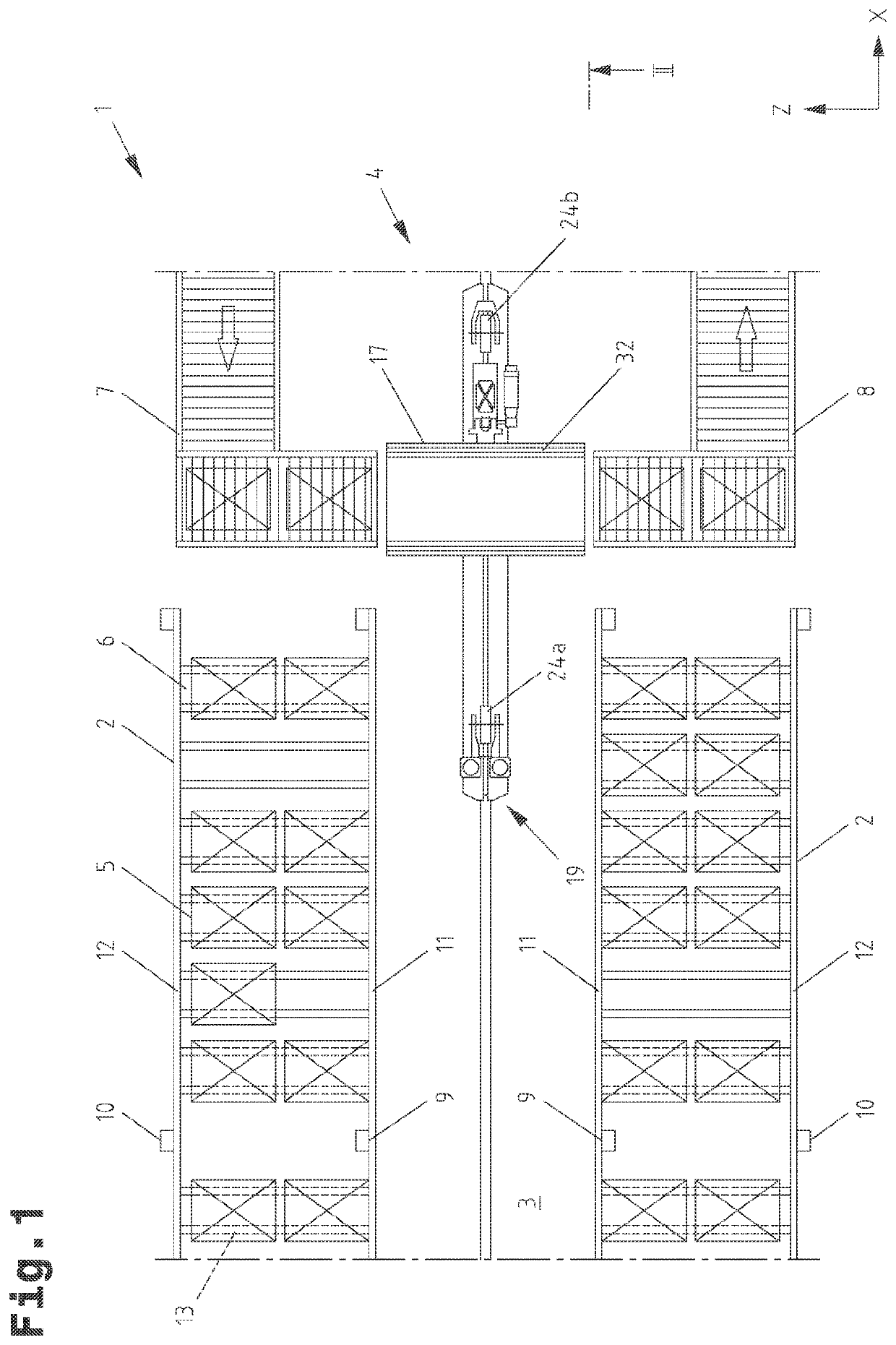
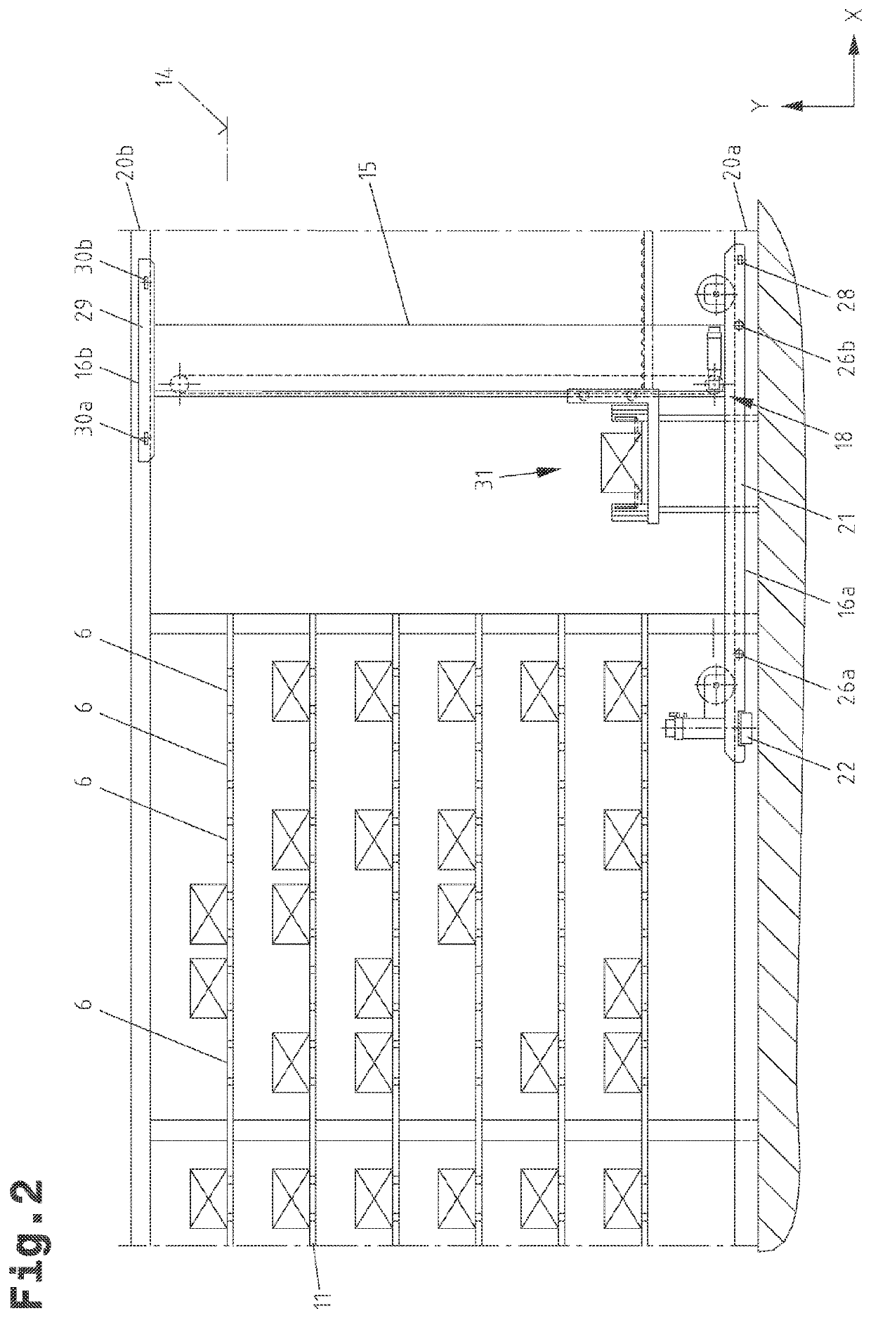
This patent describes a rail system for a conveyor vehicle that allows for a smooth transition and smooth operation of the conveyor vehicle over connected joints. The rail system includes interlocking elements and positioning openings to ensure a secure and smooth transition between rails. The rail system can be quickly mounted on rail-bracing plates using clamps and is suitable for highly dynamic conveyor vehicles and machines with high dead weight. The technical effects include increased storage and retrieval capacity, improved load on the running wheel, and reduced impact of tensile forces on the rail system.

Problems solved by technology

A subsequent machining of the running-rail connection may be unnecessary in most cases.

Method used


Image

  • Rail system for a conveying vehicle and storage system
  • Rail system for a conveying vehicle and storage system
  • Rail system for a conveying vehicle and storage system

Examples


first embodiment

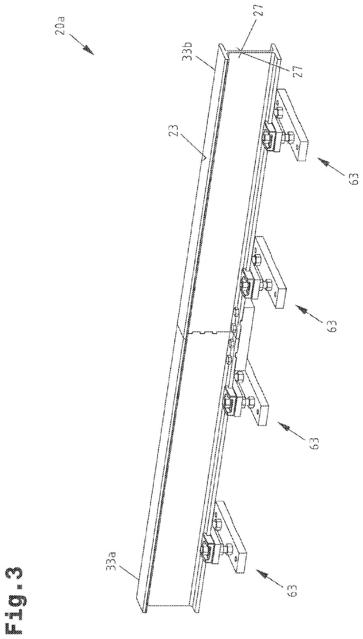
[0060]In FIGS. 3 to 10, the rail system is shown, especially the lower rail system 20a, wherein fastening devices 63 to be described in still more detail are illustrated exclusively in 3 and 4.

[0061]The rail system 20a comprises a first running rail 33a, a second running rail 33b and a connecting device 34. The connecting device 34 has at least one interlocking connection between the ends 35a, 35b, directed toward one another, of the first running rail 33a and second running rail 33b. At its end 35a, the first running rail 33a forms a first interlocking element 36a and a first surface portion 37a. The first surface portion 37a is shown in shaded manner in FIG. 8. The end 35a extends in a cross-sectional plane perpendicular to the longitudinal extent of the first running rail 33a. At its end 35b, the second running rail 33b forms a second interlocking element 36b and a second surface portion 37b. The second surface portion 37b is shown in shaded manner in FIG. 9. The end 35b extends ...

second embodiment

[0087]In FIGS. 11 to 13, described together, a rail system, especially the upper rail system 20b, which uses a similarly designed connecting device 56, is described in more detail.

[0088]The upper rail system 20b comprises a first running rail 55a, a second running rail 55b and a connecting device 56. The first running rail 55a and second running rail 55b form at least one guide track, which extends in longitudinal direction of the rail system 20b and along which one or more running wheels 30a, 30b of the conveyor vehicle 4 bear in rolling relationship. According to the shown embodiment, the running rails 55a, 55b are respectively formed by a flat profile 57, which has guide tracks 58 lying opposite one another.

[0089]As is apparent in the figures, the first surface portion 37a extends in a cross-sectional plane perpendicular to the first running rail 55a and the second surface portion 37b extends in a cross-sectional plane perpendicular to the second running rail 55b. The first surfa...


PUM


Abstract

A rail system for a conveyor vehicle capable of traveling along the rail system for storage of piece goods into a storage rack or retrieval of piece goods from a storage rack includes a first running rail, a second running rail and a connecting device, which includes a positive locking connection between the ends, directed toward one another, of the first running rail and second running rail. At its end, the first running rail forms a first interlocking element and a first surface portion. At its end, the second running rail forms a second interlocking element and a second surface portion. Therein the first interlocking element and second interlocking element engage in one another in complementary manner and the ends of the first running rail and second running rail abut at the surface portions in a butt-jointed manner. Furthermore, a warehouse system has such a rail system.

Description

CROSS REFERENCE TO RELATED APPLICATIONS[0001]This application is the National Stage of PCT / AT2017 / 060214 filed on Aug. 31, 2017, which claims priority under 35 U.S.C. § 119 of Austrian Application No. A 50818 / 2016 filed on Sep. 13, 2016, the disclosure of which is incorporated by reference. The international application under PCT article 21(2) was not published in English.BACKGROUND OF THE INVENTIONField of the Invention[0002]The invention relates to a rail system for a conveyor vehicle capable of traveling along it for storage of piece goods into a storage rack or retrieval of piece goods from a storage rack, comprising a first running rail, a second running rail and a connecting device, which comprises an interlocking connection, i.e. positive locking conection, between the ends, directed toward one another, of the first running rail and second running rail. Furthermore, the invention relates to a warehouse system having at least one storage rack and a rail system extending along ...

Claims


Application Information

Patent Timeline
Patent Type & Authority Applications(United States)
IPC IPC(8): E01B11/26E01B11/12E01B11/24E01B25/10
CPCE01B11/26E01B11/12E01B2204/06E01B25/10E01B11/24B65G1/04E01B11/20B65G1/02B65G1/0407
Inventor PREIDT, PETERRAUSCH, MARTIN
Owner TGW MECHANICS GMBH
Learn More