Autografting tool for deep reach applications

a deep-range, auto-grafting technology, applied in the field of tools, can solve the problems of complicated external irrigation protocol, difficult access to the implant placement location, etc., and achieve the effects of increasing bone toughness, increasing bone plasticity, and improving hydration of bone structur

Pending Publication Date: 2021-09-23
HUWAIS IP HLDG
View PDF0 Cites 2 Cited by
  • Summary
  • Abstract
  • Description
  • Claims
  • Application Information

AI Technical Summary

Benefits of technology

[0012]By locating the outlet orifice(s) on the stopper section of the body, an energetic feed of irrigating fluid is enabled to flow into the flutes and toward the apical end, thus better mimicking external irrigation practices of the prior art. By flowing irrigation fluid into the flutes and toward the apical end, hydraulic effects can be generated with known preconditioning advantages, which include: 1) gentle pre-stressing of the bone structure of the osteotomy in preparation for subsequent compacting contact, 2) haptic feedback transmitted through the rotary osteotome that allows the surgeon to tactically discern the instantaneously applied pressure prior to actual contact between the rotary osteotome and side walls, 3) enhanced hydration of the bone structure which increases bone toughness and increases bone plasticity, 4) hydraulically assisted infusion of bone fragments into the lattice structure of the surrounding bone, 5) reduced heat transfer especially in areas of plastic deformation, 6) hydrodynamic lubricity, and 7) dampening or cushioning of the trauma sensed by the patient, to name a few.

Problems solved by technology

In some applications, the placement location for the implant is very difficult to access.
However, the aforementioned “deep reach” situations complicate the external irrigation protocol of the Densah® bur osteotome.

Method used


Image

  • Autografting tool for deep reach applications
  • Autografting tool for deep reach applications
  • Autografting tool for deep reach applications

Examples


Embodiment Construction

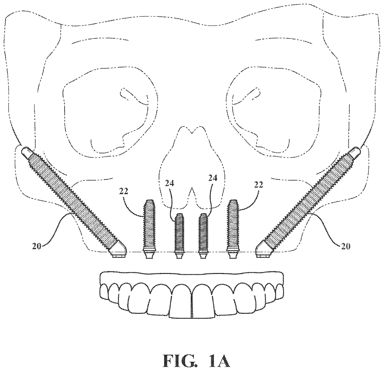
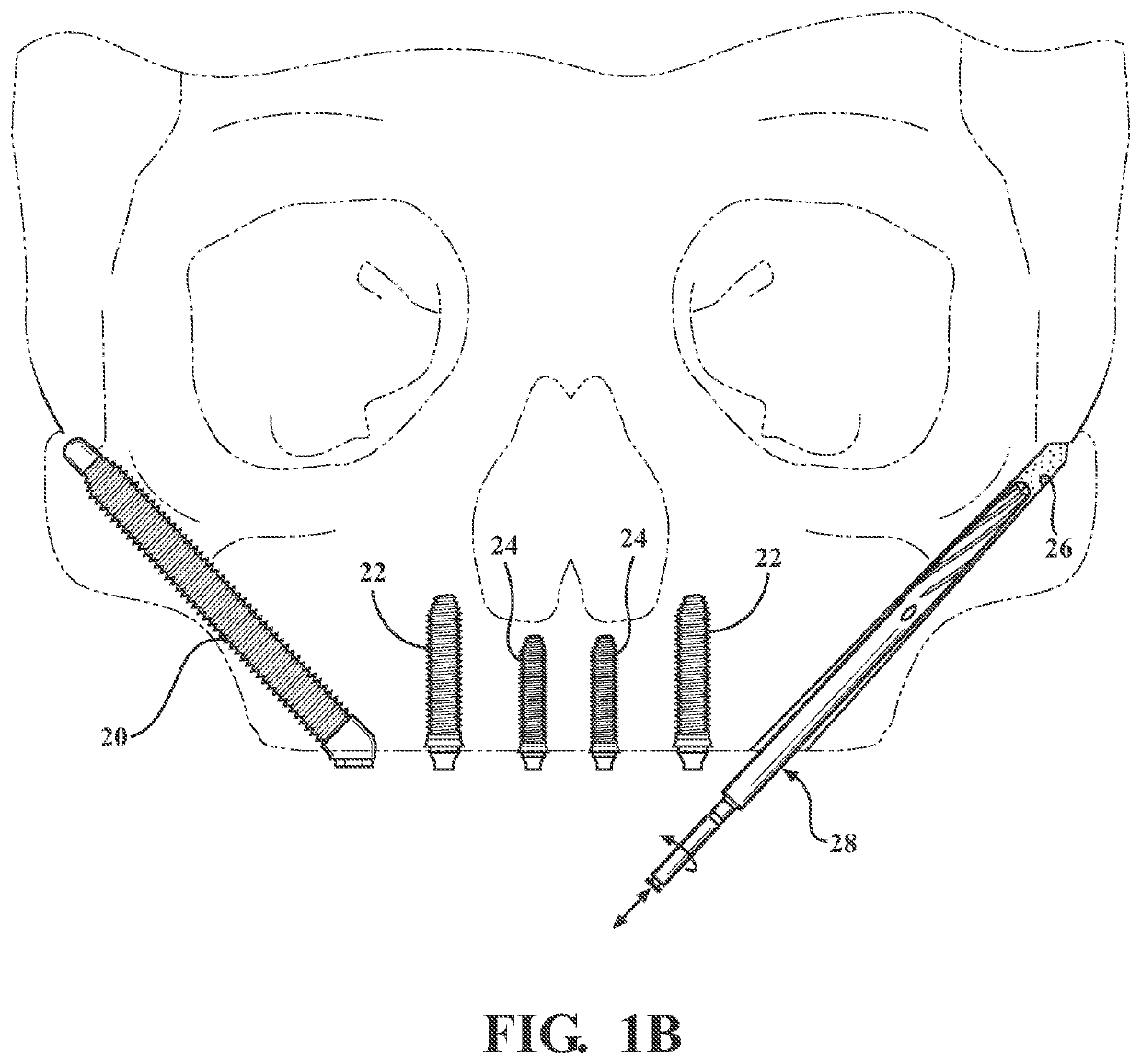
[0031]Referring to the figures, wherein like numerals indicate like or corresponding parts throughout the several views, FIGS. 1A and 1B show examples of dental implants, in which preparation of osteotomies are required to receive a bone implant 20, 22 or 24. It will be understood that this invention is not limited to dental applications, but may be applied across a wide spectrum of orthopedic applications. Human applications are typical, but animal applications are equally plausible and not outside the scope of this invention. Furthermore, the invention is not limited to bone applications, but may be used to prepare holes in organic materials like wood as well as in non-organic materials for industrial and commercial applications, including but not limited to metal foam and other cellular materials to name but a few.

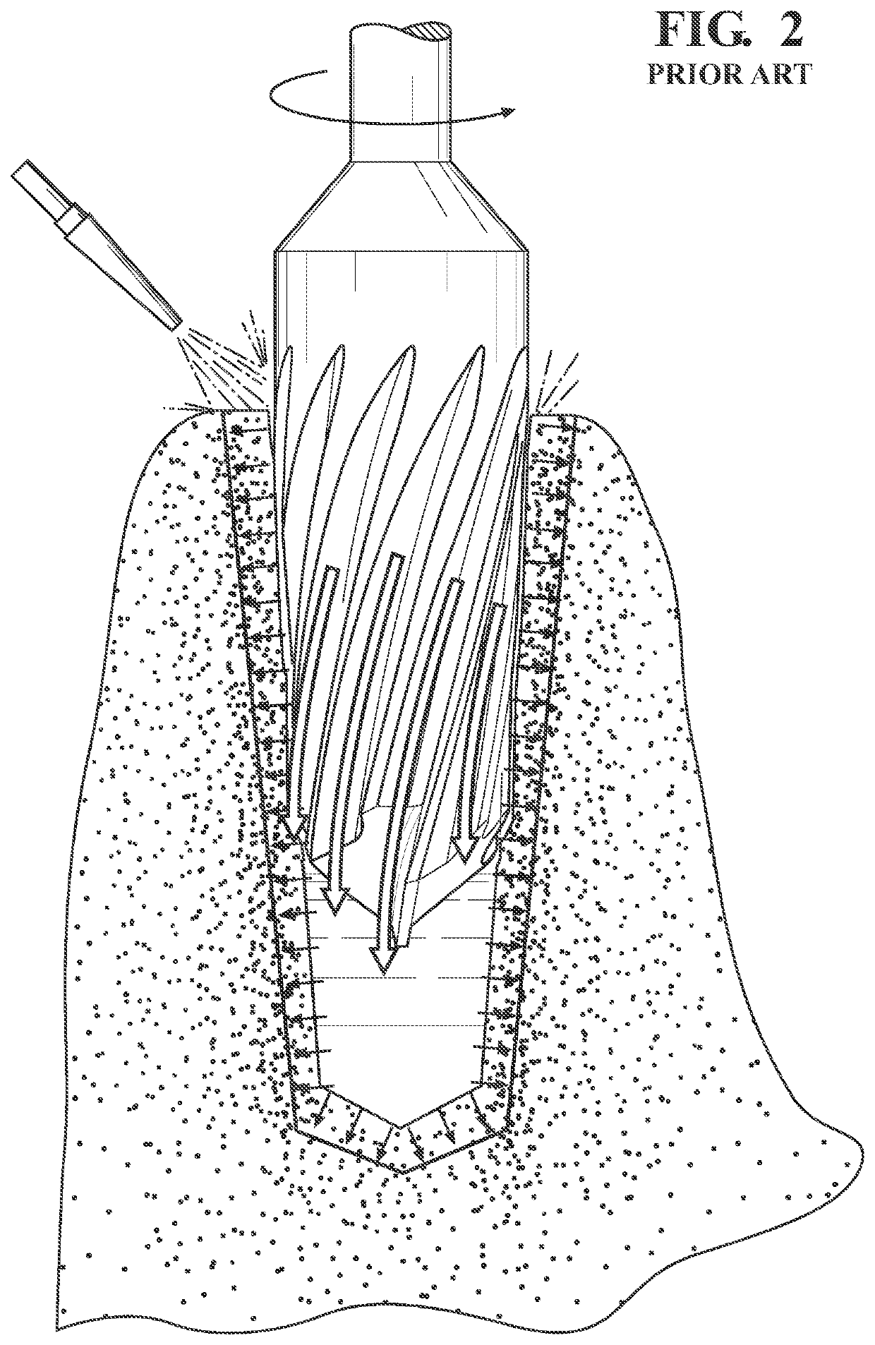
[0032]For illustrative purposes only, the externally irrigated prior art style rotary osteotome of FIG. 2 can be useful to explain the manner in which an expanded and n...


PUM


Abstract

A rotary osteotome for deep reach applications. The body of the osteotome has a tapered end that supports helically spiraling flutes. Substantially margin-less (without margin) working edges are interleaved between the flutes to provide compaction action when rotated in a non cutting direction. The body also has an elongated cylindrical stopper section. An irrigation conduit passes through the center of the stopper section and emerges at a plurality of outlet orifices that function as independent nozzles for irrigating fluid. The outlet orifices are generally elliptical in shape and spaced around the body to maintain balance. The irrigation conduit has a main trunk that opens to a flow splitter, which in turn divides the flow of irrigating fluid into substantially equal branches. Each branch is angled at an acute trajectory relative to the longitudinal axis, in the direction of said apical end, between about 10° and 45°.

Description

CROSS REFERENCE TO RELATED APPLICATIONS[0001]This application claims priority to U.S. Provisional Patent Application Ser. No. 62 / 756,406 filed on Nov. 6, 2018, the entire disclosure of which is hereby incorporated by reference and relied upon.BACKGROUND OF THE INVENTIONField of the Invention[0002]The invention relates generally to tools for preparing a hole to receive an implant or fixture, and more particularly to rotary osteotomes configured with internal irrigation.Description of Related Art[0003]An implant is a medical device manufactured to replace a missing biological structure, to support a damaged biological structure, or to enhance an existing biological structure. Bone implants are implants of the type placed into the bone of a patient. Bone implants may be found throughout the human skeletal system, including dental implants in a jaw bone to replace a lost or damaged tooth, joint implants to replace a damaged joint such as a hip or knee, and reinforcement implants install...

Claims


Application Information

Patent Timeline
Patent Type & Authority Applications(United States)
IPC IPC(8): A61C8/00
CPCA61C8/0089A61C8/0034A61B17/1615A61B2217/007A61B2017/1653A61B2017/1651A61C8/0092A61C1/08
Inventor HUWAIS, SALAH
Owner HUWAIS IP HLDG
Why Eureka
Try Eureka