Method of enhanced oil recovery using an oil heating device

a heating device and oil heating technology, applied in the direction of fluid removal, insulation, borehole/well accessories, etc., can solve the problems of large capital investment, inability to produce commercially under normal reservoir conditions economically, and restricted applications, so as to improve oil recovery and reduce oil viscosity

Active Publication Date: 2021-09-23
KING FAHD UNIVERSITY OF PETROLEUM AND MINERALS
View PDF0 Cites 0 Cited by
  • Summary
  • Abstract
  • Description
  • Claims
  • Application Information

AI Technical Summary

Benefits of technology

[0010]According to a first aspect, the present disclosure relates to a method of enhanced oil recovery, the method comprising: heating a portion of a geological formation containing an oil deposit with an oil heating device comprising a permanently-installed array of heating elements disposed at a location of a production pipe disposed in the portion of the geological formation containing the oil deposit, at a temperature sufficient to reduce the viscosity of oil in the oil deposit and flow the oil from the oil deposit into the production pipe; and recovering the oil by transporting the oil from the production pipe to the surface, wherein the permanently-installed array of heating elements comprises individual, independently-controllable heating elements.

Problems solved by technology

Heavy oil or heavy crude is a highly-viscous mixture of hydrocarbons that cannot be produced commercially under normal reservoir conditions economically.
They require large capital investments and applications are restricted by some factors including the targeted formation depth, thickness and other logistics.

Method used


Image

  • Method of enhanced oil recovery using an oil heating device
  • Method of enhanced oil recovery using an oil heating device
  • Method of enhanced oil recovery using an oil heating device

Examples


example 1

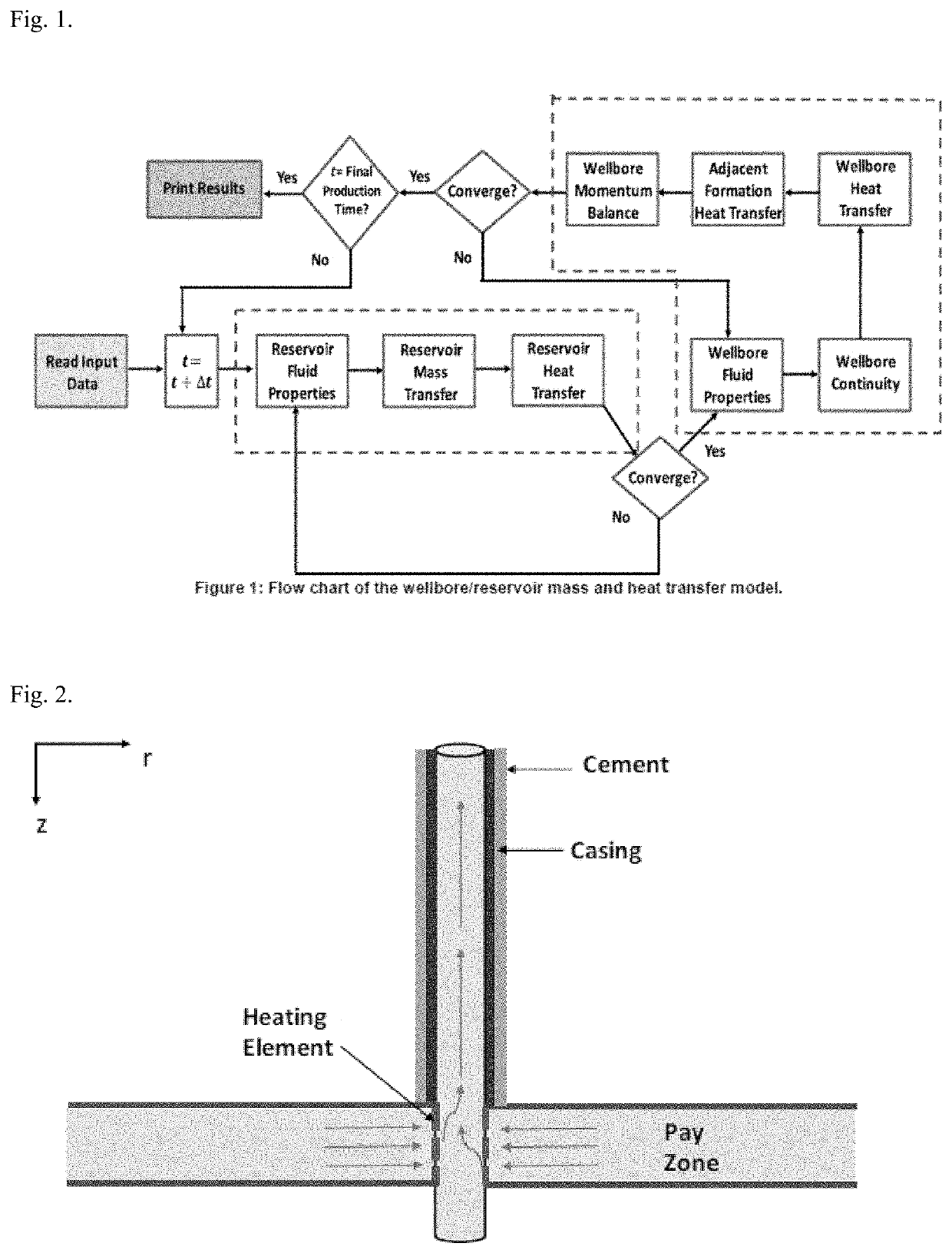
[0086]FIG. 1 shows the flow of the model which starts from reading the input data. Then, the reservoir model is applied by solving the reservoir fluid properties, pressure, and temperature until convergence. The convergence is declared when the change in two consecutive pressure and temperature profiles is negligible. The reservoir model provides the temperature of the reservoir fluids entering the wellbore. Then, the wellbore model is applied by solving the wellbore fluid properties, velocity, temperature, and pressure until convergence. This is done at each time step until reaching the final production time. The mathematical formulas for fluid properties and reservoir / wellbore model are discussed below.

Heavy Oil Fluid Properties

[0087]Different correlations were developed for the heavy oil fluid density and viscosity which varies based on the reservoir type. In this work, the heavy oil viscosity is estimated using Beggs and Robinson [Beggs, H. D., & Robinson, J., 1975, Journal of P...

example 2

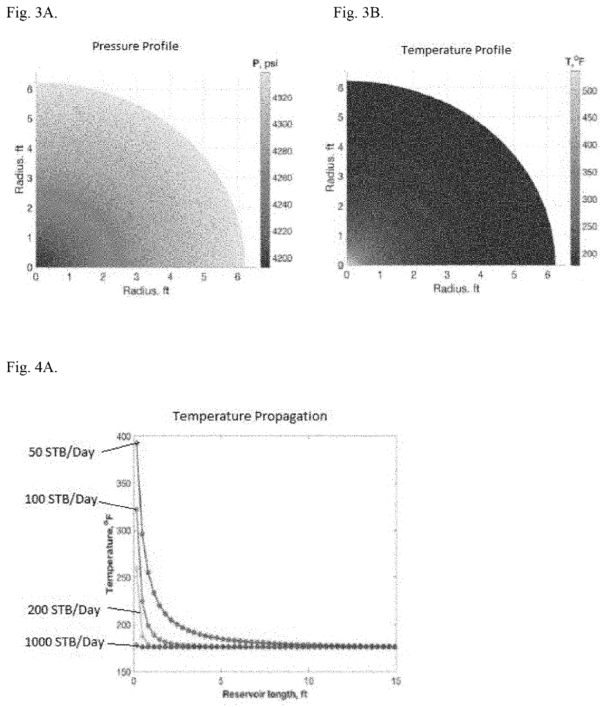
[0098]The introduced heating element can improve reservoir fluids' mobility as well as assist fluid lifting in the wellbore. Hence, the study will focus on the temperature and pressure responses of the reservoir / wellbore system before and after placing the element. The wellbore, formation, and fluids properties used in this study are shown in Table 1.

TABLE 1Input data for the integrated heat and mass transfer modelInput DataSi UnitField UnitWellbore PropertiesWellbore radius, rw0.104m0.34ftInner casing radius, Rw0.0628m2.475inchOverall heat transfer coefficient, U0.1 kJ / 0.00488 Btu / (s · m2 ·° C.)(hr · ft2 ·° F.)Heat transfer coefficient, h60 × 10−3 kJ / 2.93 × 10⁻³ Btu / (s · m2 ·° C.)(hr · ft2 ·° F.)Ambient temperature, Tb25°C.77°F.Flowing surface pressure, Ptf0.69MPa100psiWellbore length, L1220m4000ftReservoir / Formation PropertiesReservoir initial pressure, PR34.5MPa5000psiAPI gravity10  10  Reservoir temperature, TR80°C.176°F.Formation rock density, ρma2700kg / m3168.48lbm / ft3Formation...


PUM


Abstract

A method of enhanced oil recovery of using an oil heating device that is permanently-installed at the end of a production pipe down a wellbore into the pay zone of an oil deposit. The oil heating device contains an array of individually-controlled heating elements controlled by a controller. The oil heating device may also contain a plurality of sensors including array temperature sensors, oil temperature sensors, and oil flow sensors connected to the controller.

Description

BACKGROUND OF THE INVENTIONTechnical Field[0001]The present invention relates to a method of enhanced oil recovery using an oil heating device and an oil heating device comprising an array of independently-controlled heating elements.Description of the Related Art[0002]The “background” description provided herein is for the purpose of generally presenting the context of the disclosure. Work of the presently named inventors, to the extent it is described in this background section, as well as aspects of the description which may not otherwise qualify as prior art at the time of filing, are neither expressly or impliedly admitted as prior art against the present invention.[0003]Heavy oil or heavy crude is a highly-viscous mixture of hydrocarbons that cannot be produced commercially under normal reservoir conditions economically. It makes up a large portion of the world's current reserves. Thermal treatment of heavy oil can aid the exploitation of significant portions of oil resources ...

Claims


Application Information

Patent Timeline
Patent Type & Authority Applications(United States)
IPC IPC(8): E21B43/24E21B47/07E21B21/08
CPCE21B43/2401E21B21/08E21B47/07E21B36/04
Inventor AL JAWAD, MURTADAALAFNAN, SAADABU-KHAMSIN, SIDQI
Owner KING FAHD UNIVERSITY OF PETROLEUM AND MINERALS
Why Eureka
Try Eureka