Auxiliary Power Supply Circuit Operating Within a Wide Input Voltage Range

a power supply circuit and input voltage technology, applied in the direction of electric variable regulation, process and machine control, instruments, etc., can solve the problems of inability to stabilize the output voltage ripple waveform of the buck converter, affecting the operation of electronic components,

Active Publication Date: 2021-09-23
MINMAXTECH
View PDF0 Cites 0 Cited by
  • Summary
  • Abstract
  • Description
  • Claims
  • Application Information

AI Technical Summary

Benefits of technology

The present invention provides an auxiliary power supply circuit that can provide a stable working voltage to electronic components in a wide input voltage range of a DC power converter. This circuit uses a voltage follower unit and a voltage comparison unit to ensure a stable output voltage as the working voltage conversion circuit reaches its steady state. The auxiliary power supply circuit can prevent failure of electronic components due to unstable working voltage.

Problems solved by technology

However, before the Buck converter reaches a steady state (e.g.: the input voltage and the output voltage of the Buck converter approximate to each other), unstable voltage ripples occur in the waveform of the output voltage of the Buck converter actually.
Due to the unstable voltage ripples, the working voltage outputted to the electronic components is unstable, thereby directly affecting the operation of the electronic components.

Method used


Image

  • Auxiliary Power Supply Circuit Operating Within a Wide Input Voltage Range
  • Auxiliary Power Supply Circuit Operating Within a Wide Input Voltage Range
  • Auxiliary Power Supply Circuit Operating Within a Wide Input Voltage Range

Examples


Embodiment Construction

)

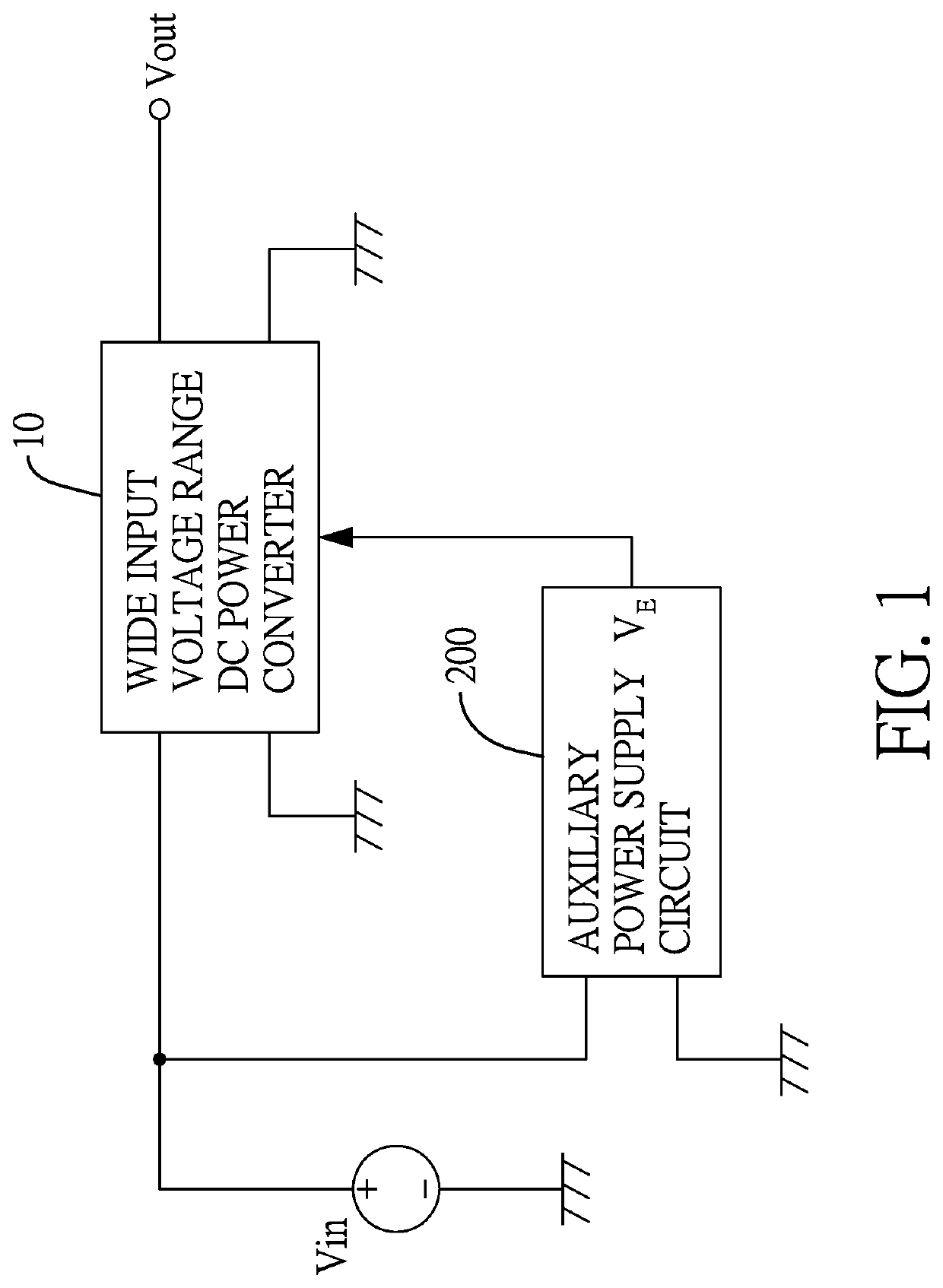
[0017]With reference to FIG. 1, the auxiliary power supply circuit 200 operating within a wide input voltage range of the present invention is applied to a wide input voltage range direct-current (DC) power converter 10. The feature of the wide input voltage range DC power converter 10 is to receive a voltage within an input voltage range from a lower-limit voltage to a higher-limit voltage and convert it to an output voltage Vout. The output voltage Vout may be retained as a constant voltage to be provided to a rear-stage circuit (load). In general, the circuit configuration of the wide input voltage range DC power converter 10 may comprise multiple electronic components, such as a transformer, a working voltage conversion circuit, an integrated circuit (IC), a feedback circuit, transistors, etc. The electronic components' working voltage is received from the working voltage conversion circuit. For example, the IC may be a pulse width modulation controller (PWM controller).

[0018]W...


PUM


Abstract

An auxiliary power supply circuit operating within a wide input voltage range has a voltage follower unit and a voltage comparison unit. The voltage follower unit has an electronic switch, a resistor, and a Zener diode. The electronic switch has a first terminal electrically connected to a voltage input terminal of the working voltage conversion circuit, a second terminal electrically connected to a voltage output terminal of the working voltage conversion circuit, and a control terminal. The resistor is electrically connected between the first terminal and the control terminal of the electronic switch. The Zener diode has a cathode electrically connected to the control terminal of the electronic switch. The voltage comparison unit has a detecting terminal electrically connected to the voltage input terminal of the working voltage conversion circuit, and an output terminal electrically connected to the control terminal of the electronic switch.

Description

CROSS REFERENCE TO RELATED APPLICATIONS[0001]The present application claims priority to Taiwan application No. 109109189, filed on Mar. 19, 2020, the content of which is hereby incorporated by reference in its entirety.BACKGROUND OF THE INVENTION1. Field of the Invention[0002]The present application relates generally to an auxiliary power supply circuit, and more particularly to an auxiliary power supply circuit operating within a wide input voltage range.2. Description of Related Art[0003]The feature of a wide input voltage range direct-current (DC) power converter is to receive an input voltage within an input voltage range from a lower-limit voltage to a higher-limit voltage and convert it to an output voltage. The output voltage may maintain a constant for being provided to a rear-stage circuit (load). For example, the circuit configuration of the wide input voltage range DC power converter may comprise multiple electronic components, such as a transformer, a working voltage con...

Claims


Application Information

Patent Timeline
IPC IPC(8): H02M3/158G01R19/165H03K5/24H02M1/32G05F3/18H02M1/10
CPCH02M3/158G01R19/16538H03K5/24H02M2001/0025G05F3/18H02M1/10H02M1/32H02M1/36H02M1/15G05F1/468G05F1/613G05F3/185H02M1/0006H02M1/0045
InventorWU, CHENG-CHOU
OwnerMINMAXTECH