Communication system, communication terminal, and base station

Pending Publication Date: 2021-09-23
MITSUBISHI ELECTRIC CORP
View PDF0 Cites 0 Cited by
  • Summary
  • Abstract
  • Description
  • Claims
  • Application Information

AI Technical Summary

Benefits of technology

The patent provides a way to have radio communication with low delays.

Problems solved by technology

The RACH involves a collision risk.

Method used


Image

  • Communication system, communication terminal, and base station
  • Communication system, communication terminal, and base station
  • Communication system, communication terminal, and base station

Examples


first embodiment

The First Embodiment

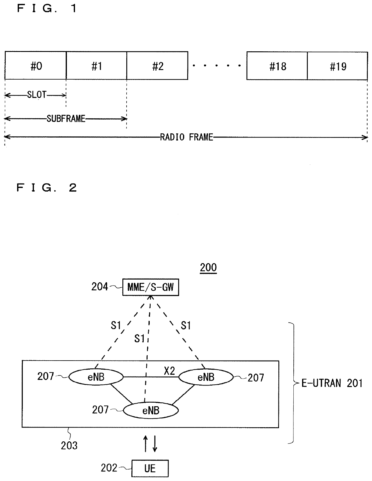
[0101]FIG. 2 is a block diagram showing an overall configuration of an LTE communication system 200 which is under discussion of 3GPP. FIG. 2 is described here. A radio access network is referred to as an evolved universal terrestrial radio access network (E-UTRAN) 201. A user equipment device (hereinafter, referred to as a “user equipment (UE)”) 202 that is a communication terminal device is capable of radio communication with a base station device (hereinafter, referred to as a “base station (E-UTRAN Node B: eNB)”) 203 and transmits and receives signals through radio communication.

[0102]Here, the “communication terminal device” covers not only a user equipment device such as a mobile phone terminal device, but also an unmovable device such as a sensor. In the following description, the “communication terminal device” may be simply referred to as a “communication terminal”.

[0103]The E-UTRAN is composed of one or a plurality of base stations 203, provided that a ...

second embodiment

[0181]In downlink data reception, the gNB may notify the UE of the number of slots from downlink data reception by the UE to a HARQ response from the UE by using L1 / L2 signaling. The gNB may notify the UE of candidates of the number of slots in advance. For the notification of the candidates, for example, RRC signaling may be used. The gNB may select the number of slots from downlink data reception by the UE to a HARQ response from the UE out of the candidates and notify the UE. For the notification of the selected number of slots, for example, L1 / L2 signaling may be used. The number of slots may be notified by being included in DCI including downlink scheduling information from the gNB to the UE.

[0182]When the method described above is applied before and after TRP switch, a problem described below is caused. For example, due to switch to an asynchronous TRP, a backhaul delay amount between the gNB and the TRP is changed. With this, between the UE and the gNB, time from downlink dat...

third embodiment

[0196]The UE may transmit the SRS of a plurality of symbols in one subframe. The SRS transmission may be used in LTE. The base station may perform configuration of transmitting a plurality of SRS symbols to the UE. The UE may transmit a plurality of SRS symbols by using the configuration.

[0197]In the description above, a problem described below is caused. Specifically, in a conventional SRS configuration (see Non-Patent Document 22) disclosed in Non-Patent Document 22, only a configuration of transmitting the SRS using only one symbol at the end of a subframe is performed. As a result, the base station cannot configure transmission of a plurality of SRS symbols in one subframe for the UE, and further, the UE cannot transmit a plurality of SRS symbols in one subframe.

[0198]A method for solving the problem described above will be disclosed.

[0199]In SRS configuration, information related to SRS transmission symbols is added. In the information, information related to a start symbol of ...


PUM


Abstract

A radio communication technology with small delay is provided. A communication system includes a communication terminal and a base station. The base station includes a plurality of transmitter-receivers configured to perform radio communication with the communication terminal. The base station is configured to perform radio communication with the communication terminal by using a part or all of the plurality of transmitter-receivers. The communication terminal receives a downlink synchronization signal from at least one transmitter-receiver to be newly connected, and establishes downlink synchronization with the at least one transmitter-receiver by using the downlink synchronization signal. The communication terminal receives a random access start order from the base station, performs random access processing by using the random access start order, and establishes uplink synchronization with the at least one transmitter-receiver.

Description

TECHNICAL FIELD[0001]The present invention relates to a radio communication technology.BACKGROUND ART[0002]The 3rd generation partnership project (3GPP), the standard organization regarding the mobile communication system, is studying communication systems referred to as long term evolution (LTE) regarding radio sections and system architecture evolution (SAE) regarding the overall system configuration including a core network and a radio access network which is hereinafter collectively referred to as a network as well (for example, see Non-Patent Documents 1 to 5). This communication system is also referred to as 3.9 generation (3.9 G) system.[0003]As the access scheme of the LTE, orthogonal frequency division multiplexing (OFDM) is used in a downlink direction and single carrier frequency division multiple access (SC-FDMA) is used in an uplink direction. Further, differently from the wideband code division multiple access (W-CDMA), circuit switching is not provided but a packet co...

Claims


Application Information

Patent Timeline
IPC IPC(8): H04W56/00H04W74/08H04L1/18
CPCH04W56/001H04L1/1812H04W74/0833H04W56/0015H04W88/085H04L1/1854H04L1/1896H04B7/022
Inventor TANAKA, TOSHIKISHIMODA, TADAHIROMOCHIZUKI, MITSURU
Owner MITSUBISHI ELECTRIC CORP
Why Eureka
Try Eureka