Method and device for controlling power output stage

A technology for controlling power and power, which is applied in the field of devices realizing the method, can solve problems such as delayed switching processes, and achieve the effect of little circuit delay

Inactive Publication Date: 2004-07-07
SIEMENS AG
View PDF2 Cites 0 Cited by
  • Summary
  • Abstract
  • Description
  • Claims
  • Application Information

AI Technical Summary

Problems solved by technology

However, this significantly delays the switching process described, that is to say the transition from the OFF state to the ON state or vice versa.

Method used


Image

  • Method and device for controlling power output stage
  • Method and device for controlling power output stage
  • Method and device for controlling power output stage

Examples


Embodiment Construction

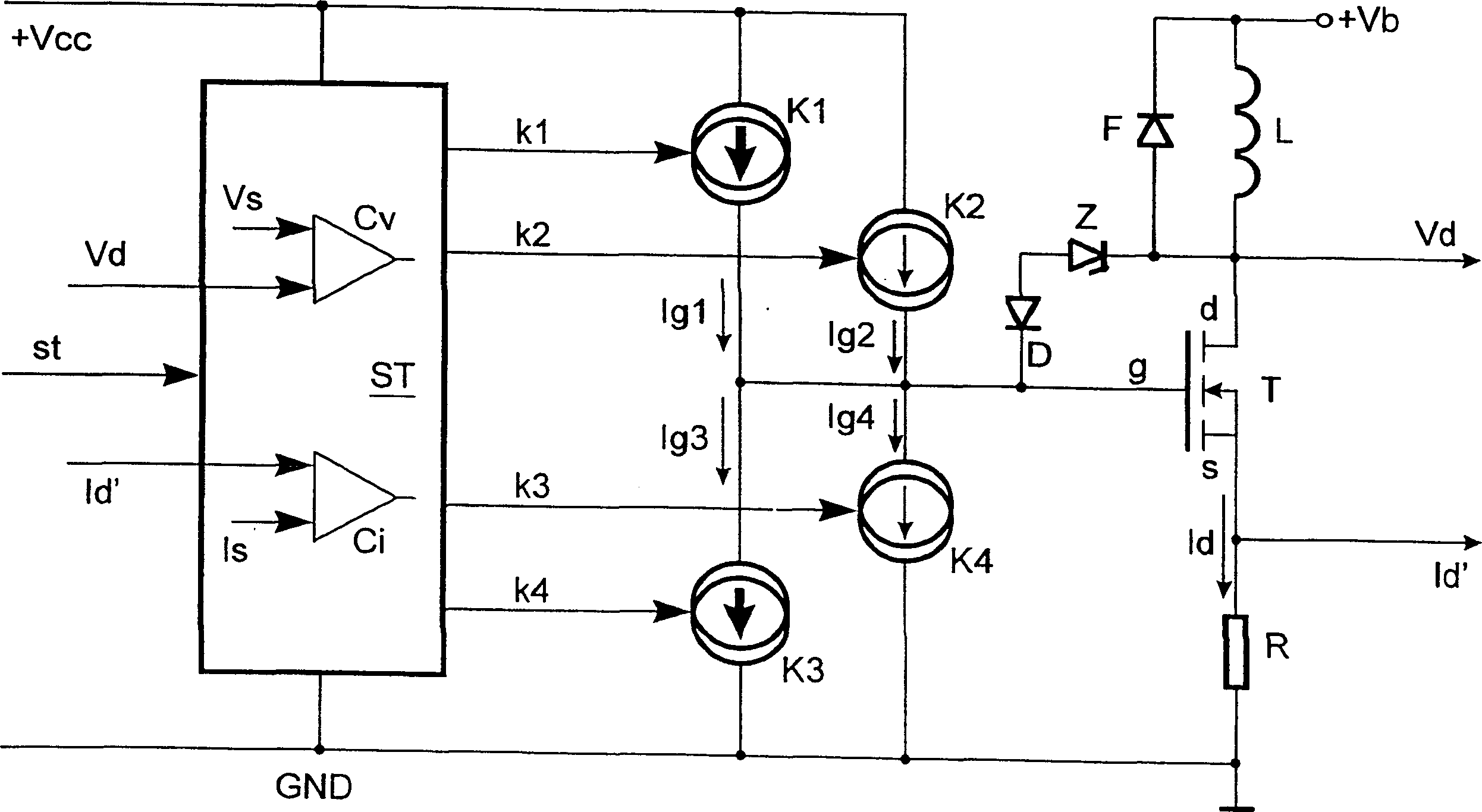
[0018] Such as figure 1 As shown, the invention will be described below with the aid of a pulsed power output stage integrated in an integrated circuit for use in a vehicle, which is used to switch an inductive load L with a freewheeling diode F. The integrated power output stage can be accommodated, for example, in a motor controller (not shown), which receives the control signal st from the motor controller in order to switch on and off in a pulsed fashion, for example for exhaust gas feedback Regulates the inductive load L of the valve. The opening size of the valve is controlled according to the adjusted pulse duty cycle.

[0019] Connected to a voltage source (not shown), such as pole +Vb and GND of a vehicle battery, is a series circuit consisting of an inductive load L and a power switch T implemented as a MOSFET.

[0020] The load L is located between the drain d of the power switch T and the positive pole +Vb of the voltage source. The source s is connected to the ...


PUM


Abstract

The invention relates to a power output stage (T) which is charged with a high charging current (Ig1) in order to effect an electromagnetic interference-compatible control. The power output stage is charged until the drain current (Id) exceeds a current threshold value (Is), is subsequently charged with a lower charging current (Ig2), said lower charging current being associated with the desired slew rate, until the drain voltage (Vd) falls below a predetermined voltage threshold value (Vs), and, afterwards, is subjected to a continual charging with the high charging current(Ig1) for a predetermined duration (Tv). To effect a closing control, the operation is carried out in an almost reversed sequence.

Description

technical field [0001] The invention relates to a method for controlling a power output stage by means of a control signal in order to switch a load connected in series to the poles of a voltage source via a MOSFET power switch. The invention also relates to a device for implementing the method. Background technique [0002] To control inductive loads, power output stages with transistors, in particular MOSFET transistors, are used as power switches. When turning off the transistor, the energy of the inductive load must be dissipated by the Zener action of the final stage or dissipated by the free-wheeling diode. In cases where the load has high inductive energy, use a freewheeling diode across the load. A disadvantage of such an output stage, especially a pulsed output stage, is that it causes considerable electromagnetic interference. [0003] One known reason is that the voltage at the connection point between the load and the power switch changes rapidly. This is the...

Claims


Application Information

Patent Timeline
Patent Type & Authority Patents(China)
IPC IPC(8): H03K17/042H03K17/16H03K17/695
CPCH03K17/166H03K17/04206H02H3/00
Inventor J·法尔特M·埃利奥特C·布兰多
Owner SIEMENS AG
Why Eureka
Try Eureka