
Method for manufacturing a part

a manufacturing method and technology for parts, applied in the field of manufacturing, can solve the problems of increasing the cost and time of fabrication, high recurring/non-recurring costs associated with these conventional manufacturing techniques, and predetermining the production rate of aircraft, so as to reduce water ingestion problems, improve dimensional tolerances, and improve tightness

Inactive Publication Date: 2021-09-30
AIRBUS OPERATIONS SL
View PDF3 Cites 1 Cited by
  • Summary
  • Abstract
  • Description
  • Claims
  • Application Information

AI Technical Summary

Benefits of technology

The patent text describes a method for printing using different types of filaments. The height of each layer on the part is set using the tools of the printer. If the layer is made thicker, the part will have less fine detail and the layers will be more visible. Conversely, if the layer is made thinner, the part will have higher detail but will take longer to produce. Additionally, the method allows for the selective deposition of additional types of filaments, making it more versatile for different applications.

Problems solved by technology

This constitutes a time-demanding process predetermining the production rate of aircrafts.
As a consequence, the final component is achieved after a series of different manufacturing steps that increment the cost and time of fabrication.
This drawback, along with the high recurring / non-recurring costs associated to these conventional manufacturing techniques, has promoted the advent of Additive Manufacturing (AM) technologies in aeronautics.
Nevertheless, the mechanical properties of printed composite parts for aircraft tend to be inferior to the properties of the same parts made from aluminum or composite materials manufactured by conventional techniques (non-AM).
AM printed parts tend to have defects, such as voids, porosity and poor adhesion between the printed filaments in the same layer or in adjacent layers.
Another typical local defect in an AM printed part is an absence of polymer chain interfusion between adjacent filaments which results in a low inter-laminar shear strength (‘ILSS’) that weakens the printed parts and makes the parts susceptible to failure when subjected to certain stresses.
When AM printed parts are tested or put into service, the voids and printing defects in the parts may act as stress concentrators causing the parts to fail prematurely.
More recent solutions rely on vacuum beds to assist the printing process but, although consolidated pieces may be obtained, tight dimensions are not achievable with vacuum beds.
It is not always possible to benefit from these available compaction solutions because complex geometries being printed prevent uniform rolling of the part and because some printing tools are not compatible with the conventional compaction equipment.

Method used


Image

  • Method for manufacturing a part
  • Method for manufacturing a part

Examples


Embodiment Construction

lass="d_n">[0083]The person skilled in the art should recognize that aspects described herein can be embodied either as a method for manufacturing a part, or as the part itself.

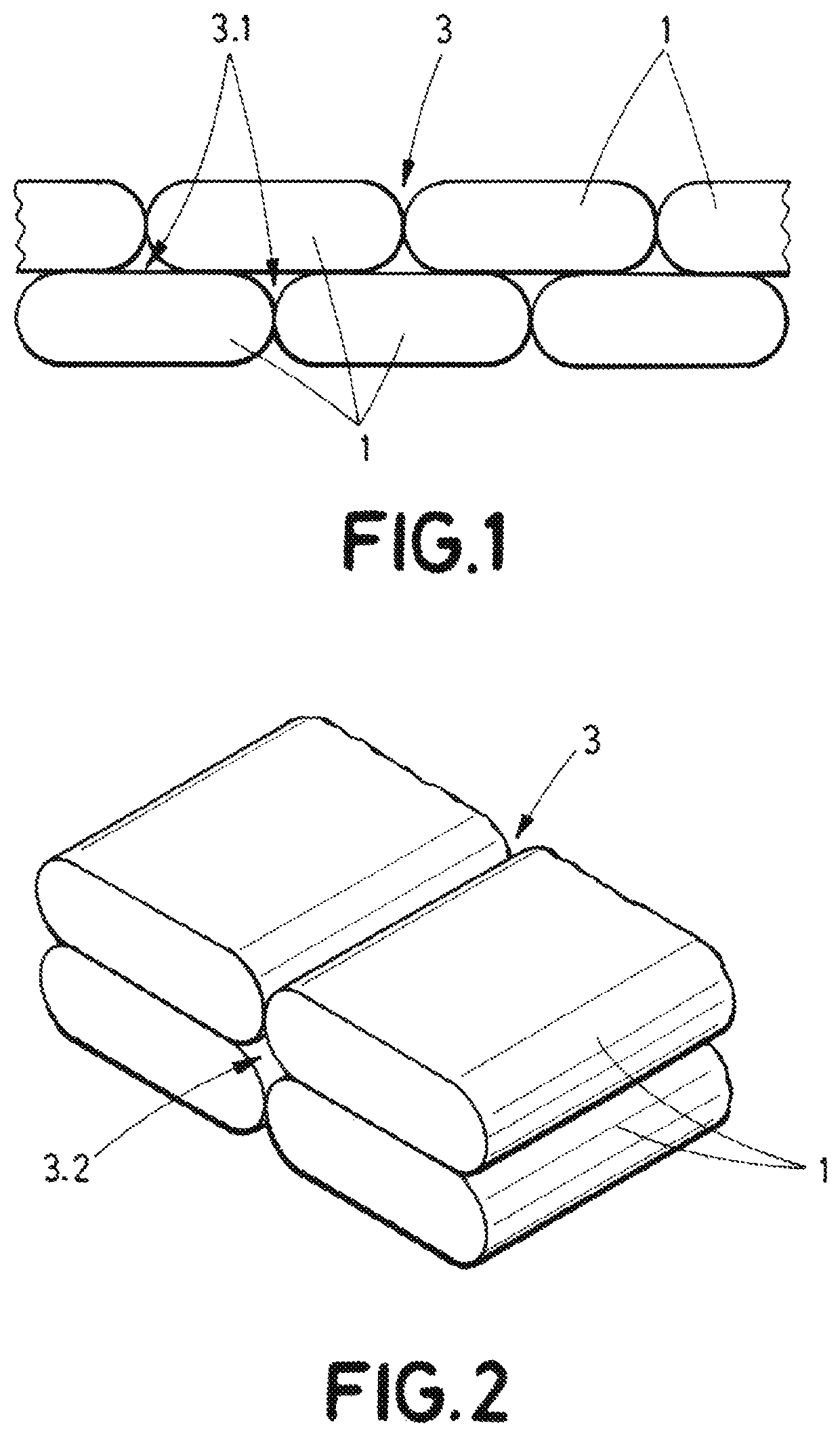
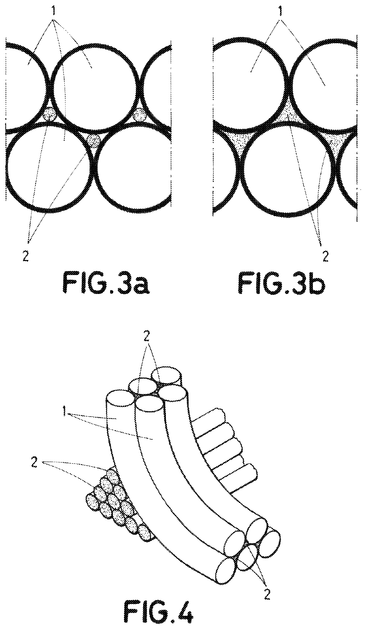
[0084]A method for manufacturing a part layer-upon-layer using Additive Manufacturing technology has been invented and disclosed herein. The method includes performing at least once the steps of: (a) forming a layer by depositing first type filaments, at least a portion of the first type filaments (1) being deposited alongside each other thus creating at least one channel (3), and (b) depositing at least a portion of a second type filament (2) along, e.g., in, said channel (3), wherein the second type filament (2) differs from the first type filament (1) at least in the cross-sectional dimension.

[0085]The method may use an additive manufacturing tool comprising a printing chamber housing a build sheet and at least one print head configured to move over the build sheet and to deposit selectively the first type...


PUM

PropertyMeasurementUnit
cross-sectional dimensionaaaaaaaaaa
shapeaaaaaaaaaa
volume contentaaaaaaaaaa

Abstract

A method for manufacturing a part layer-upon-layer using Additive Manufacturing technology suitable for structural applications. The method includes selectively depositing at least a first type filament and a second type filament, wherein the second type filament differs from the first type filament at least in the cross-sectional dimension.

Description

RELATED APPLICATION[0001]This application claims priority to European Patent Application 20382229-1, filed Mar. 25, 2020, the entirety of which is incorporated by reference.TECHNICAL FIELD[0002]The present invention belongs to the field of manufacturing, in particular to the field of manufacturing parts with low or no porosity by using an Additive Manufacturing technology.[0003]More specifically, the invention is of special application in the manufacturing of printed parts for structural applications where conventional compaction is not feasible.BACKGROUND OF THE INVENTION[0004]Historically, aircraft parts with structural applications have been made of aluminum alloys. In recent decades, with the development of composite manufacturing technologies, such structural parts have been manufactured with different techniques such as, co-bonding or co-curing of Carbon Fiber Reinforced Plastic (CFRP) constituent parts.[0005]Nevertheless, all these manufacturing technologies require that the ...

Claims


Application Information

Patent Timeline
Patent Type & Authority Applications(United States)
IPC IPC(8): B29C64/118B33Y10/00B33Y70/00
CPCB29C64/118B29K2105/124B33Y70/00B33Y10/00B29C64/124B29C64/209B29C64/188B29C64/236B29C64/386B33Y30/00B33Y40/00B33Y50/00B29K2101/12B29K2507/04
Inventor BUTRAGUENO-MARTINEZ, ASUNCIONHERNAIZ LOPEZ, GUILLERMOSANCHEZ-GOMEZ, JOSE
Owner AIRBUS OPERATIONS SL
Learn More