Eureka AIR delivers breakthrough ideas for toughest innovation challenges, trusted by R&D personnel around the world.

Vehicle control device

a technology of vehicle control and control device, which is applied in the direction of electric control, machines/engines, transportation and packaging, etc., can solve the problems of increasing the upper limit value of limiting the output of the engine, etc., and achieves the effect of increasing the rotation speed of the engine, increasing the gear ratio, and increasing the torque of the engin

Inactive Publication Date: 2021-09-30
TOYOTA JIDOSHA KK
View PDF0 Cites 0 Cited by
  • Summary
  • Abstract
  • Description
  • Claims
  • Application Information

AI Technical Summary

Benefits of technology

The patent text describes a configuration for a vehicle that allows for more power generation by the engine and reduces the amount of power needed from the motor generator. This is achieved by increasing the output of the engine and adjusting the air-fuel ratio in the cylinders to a rich side, which increases the torque of the engine. This results in a larger amount of power available for the vehicle to use, preventing power from being too low for the driver. Additionally, the configuration prevents the output of the engine from being too high, which could cause power to be wasted. Overall, this technology improves the performance and efficiency of vehicles.

Problems solved by technology

When the rotation speed of the engine is uniquely determined, the upper limit value of the output of the engine is likely to be restricted.
As a result, the upper limit value of the output of the engine can be raised by increasing the torque of the engine.

Method used


Image

  • Vehicle control device
  • Vehicle control device
  • Vehicle control device

Examples


Embodiment Construction

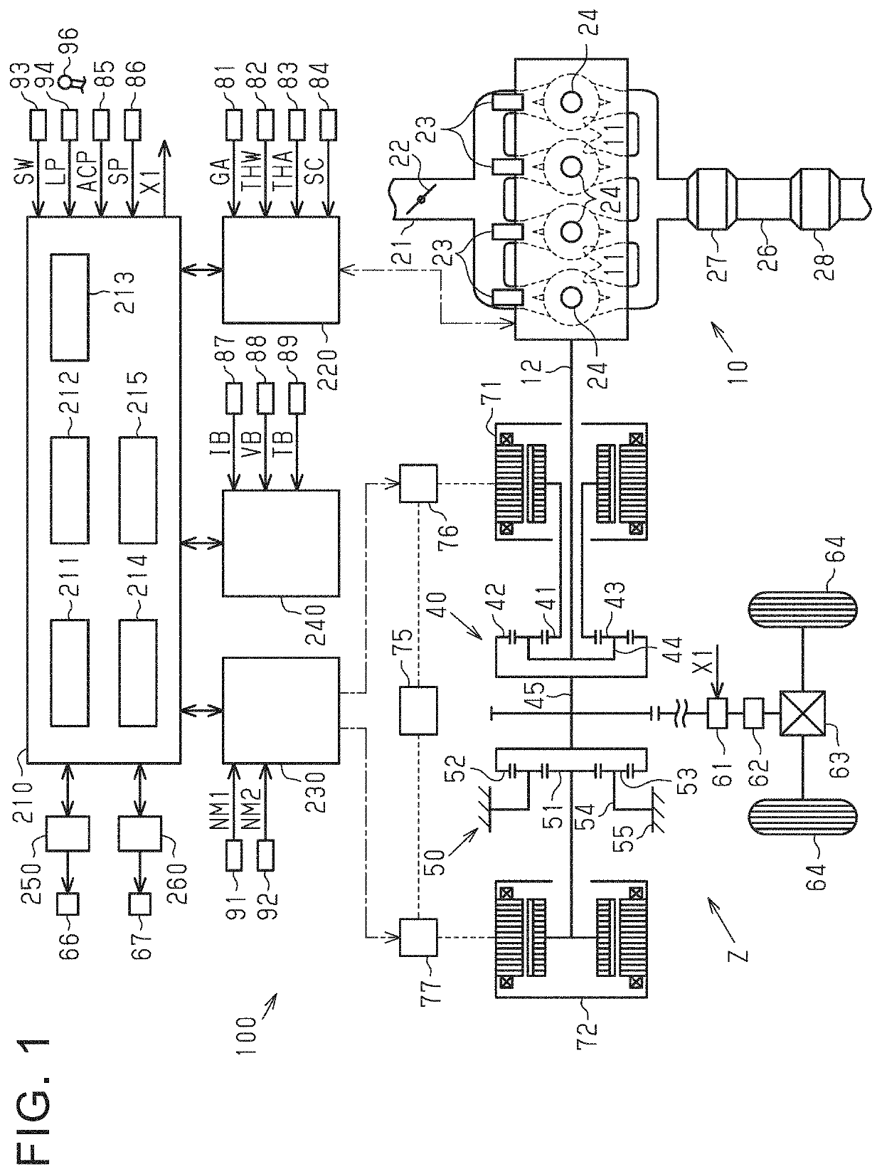
[0027]Hereinafter, an embodiment of the vehicle control device will be described with reference to FIGS. 1 to 5. First, the schematic configuration of a vehicle 100 will be described. As shown in FIG. 1, the vehicle 100 includes a spark-ignition engine 10. The vehicle 100 includes a first motor generator 71 and a second motor generator 72, which are two motor generators each having both functions of an electric motor and a generator. Therefore, the vehicle 100 is a so-called hybrid vehicle.

[0028]The engine 10 includes a plurality of cylinders 11, a crankshaft 12, an intake passage 21, a throttle valve 22, a plurality of fuel injection valves 23, a plurality of ignition devices 24, an exhaust passage 26, a three-way catalyst 27, and a filter 28.

[0029]In the cylinder 11, the air-fuel mixture of the fuel and the intake air burns. The engine 10 includes four cylinders 11. The intake passage 21 is connected to the cylinders 11. The downstream portion of the intake passage 21 is branched ...


PUM


Abstract

The present disclosure relates to a control device for a vehicle. The vehicle includes an engine as a drive source, a motor generator as a drive source, a battery for storing electric power generated by the motor generator using an output of the engine, and an exhaust treatment device provided in an exhaust passage of the engine. The control device is configured to execute a temperature rise control that increases the output of the engine and raises a temperature of exhaust gas flowing into the exhaust treatment device.

Description

CROSS-REFERENCE TO RELATED APPLICATION[0001]This application claims priority to Japanese Patent Application No. 2020-063963 filed on Mar. 31, 2020, incorporated herein by reference in its entirety.BACKGROUND1. Technical Field[0002]The present disclosure relates to a vehicle control device.2. Description of Related Art[0003]A vehicle described in Japanese Unexamined Patent Application Publication No. 2017-149233 (JP 2017-149233 A) includes an engine and a motor generator as a drive source. The vehicle is equipped with a battery that stores electric power generated by the motor generator using the output of the engine. The vehicle is equipped with a filter located in an exhaust passage of the engine. The filter collects particulate matter flowing through the exhaust passage.[0004]The vehicle control device increases the output of the engine when performing temperature rise control that raises the temperature of the exhaust gas flowing into the filter to burn the particulate matter in ...

Claims


Application Information

Patent Timeline
Patent Type & Authority Applications(United States)
IPC IPC(8): B60W10/30B60W10/06B60W10/10F01N3/021F01N9/00B60W20/30
CPCB60W10/30B60W10/06B60W10/10F01N3/021B60H1/00878B60W20/30F01N2900/08F01N2590/11F01N9/00B60W20/15B60W2510/08F01N3/023F01N3/101F01N9/002F01N2430/00F01N2900/1404B60H1/3208B60H2001/3273Y02T10/12Y02T10/40F02D2041/026F02D41/0245Y02A50/20B60K6/445B60W10/08B60W20/16B60W2540/10B60W2710/0677B60W2710/086B60W2710/0694Y02T10/62B60W2710/30B60W2510/0676B60W2710/0688B60W2710/10
Inventor HIASA, YASUHIROTSUCHIDA, YASUTAKA
Owner TOYOTA JIDOSHA KK
Why Eureka
Eureka Blog
Learn More