Control apparatus for AC-AC converter
a control apparatus and converter technology, applied in the direction of electric variable regulation, process and machine control, instruments, etc., can solve the problems of loss of motors, noise or destruction of motors, and torque pulsation ascribable to low frequency components below input frequencies exerting serious influence, etc., to reduce the distortion of low frequency output voltage, enhance the effect of voltage transfer ratio, and suppress the increase of output curren
- Summary
- Abstract
- Description
- Claims
- Application Information
AI Technical Summary
Benefits of technology
Problems solved by technology
Method used
Image
Examples
first embodiment
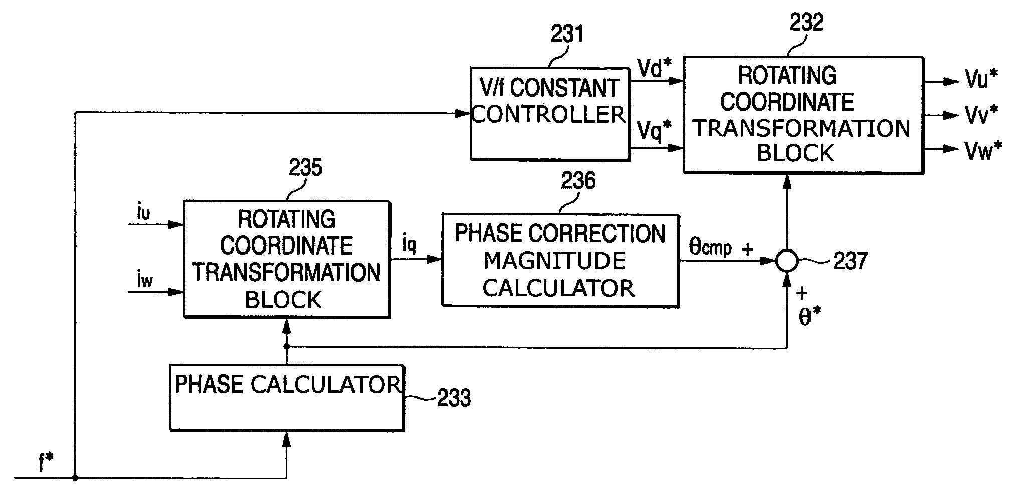
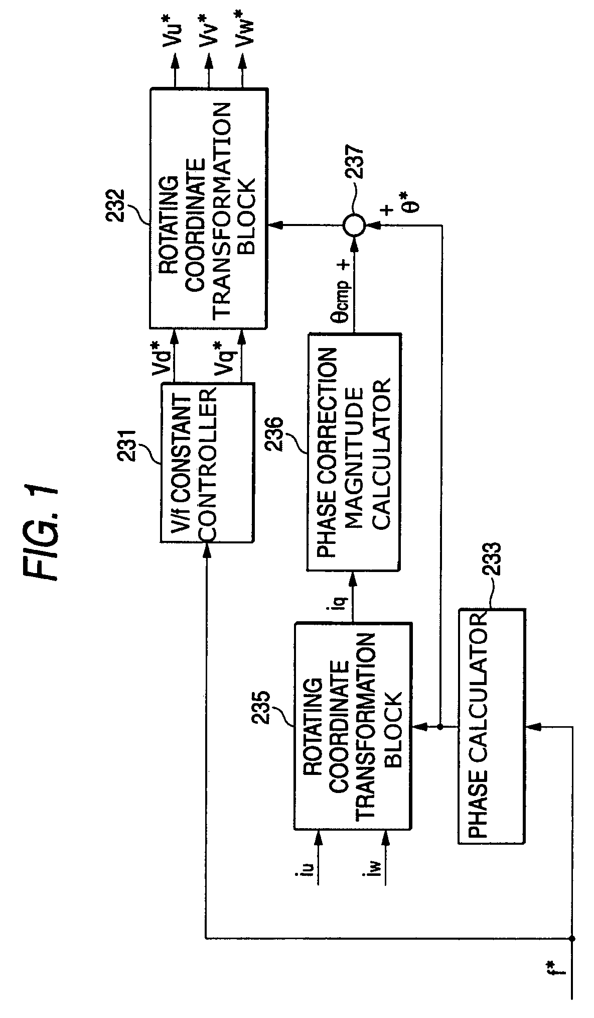
[0037]FIG. 1 shows the invention, which includes improvements in the internal configuration of the virtual inverter command calculator 23 in FIG. 9. Here, the same elements as those in FIG. 10 shall be designated by the same reference characters.
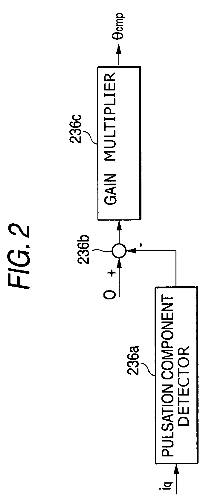
[0038]Referring to FIG. 1, a d-axis voltage command value vd* and a q-axis voltage command value vq* are calculated from a frequency command f*, as similarly shown in FIG. 10. Output phase currents iu and iw detected from a direct converter, e.g., a matrix converter, and a phase command θ* outputted from the phase calculator 233, are inputted to rotating coordinate transformation block 235 that calculates a q-axis current iq that is one of two currents components of two orthogonal axis. Also in phase correction magnitude calculator 236, a pulsation component is detected from the q-axis current iq, so as to obtain a correction magnitude θcmp for correcting the phase command θ* of an output voltage. The correction magnitude θcmp is added to th...
second embodiment
[0047]FIG. 5 is a block diagram showing the invention in which a phase correction magnitude θcmp is calculated by using the absolute value of an output current vector. Absolute value calculator 238 calculates the absolute value (=√(id2+iq2)) of the output current vector using the currents id and iq outputted from rotating coordinate transformation block 235. Phase correction magnitude calculator 236 calculates the phase correction magnitude θcmp using the absolute value.
third embodiment
[0048]Next, FIG. 6 is a block diagram showing principal portions of the invention. The embodiment of FIG. 6 is different from that of FIG. 1 in that a frequency correction magnitude fcmp calculated from the pulsation component of a q-axis current iq by frequency correction magnitude calculator 239 is added to the frequency command f* of the output voltage by adder / subtractor 237. The frequency correction magnitude calculator 239 can be realized by the same configuration as shown in FIG. 2. The calculator 239 outputs the correction magnitude fcmp for correcting the frequency command f* on the basis of the pulsation component of the q-axis current iq. The adder / subtractor 237 provides a corrected output voltage frequency command (f*+fcmp) by adding the correction magnitude fcmp to the frequency command f*. The corrected frequency command is inputted to phase calculator 234, which obtains the final phase command θ** of the output voltage by using the corrected frequency command. Then, ...
PUM
 Abstract
Description
Claims
Application Information
 - R&D
- Intellectual Property
- Life Sciences
- Materials
- Tech Scout
- Unparalleled Data Quality
- Higher Quality Content
- 60% Fewer Hallucinations
Browse by: Latest US Patents, China's latest patents, Technical Efficacy Thesaurus, Application Domain, Technology Topic, Popular Technical Reports.
© 2025 PatSnap. All rights reserved.Legal|Privacy policy|Modern Slavery Act Transparency Statement|Sitemap|About US| Contact US: help@patsnap.com


