Overcurrent limiting circuit, overcurrent limiting method, and power supply circuit

Active Publication Date: 2019-08-08
ABLIC INC
View PDF15 Cites 3 Cited by
  • Summary
  • Abstract
  • Description
  • Claims
  • Application Information

AI Technical Summary

Benefits of technology

[0013]According to the present invention, there can be provided an overcurrent limiting circuit, an overcurrent limiting method, and a power supply circuit capable of, when large current flows th

Problems solved by technology

However, since the overcurrent limiting circuit of Japanese Patent Application Laid-Open No. 2009-48362 controls the output current based on the reduction in the output vol

Method used


Image

  • Overcurrent limiting circuit, overcurrent limiting method, and power supply circuit
  • Overcurrent limiting circuit, overcurrent limiting method, and power supply circuit
  • Overcurrent limiting circuit, overcurrent limiting method, and power supply circuit

Examples


first embodiment

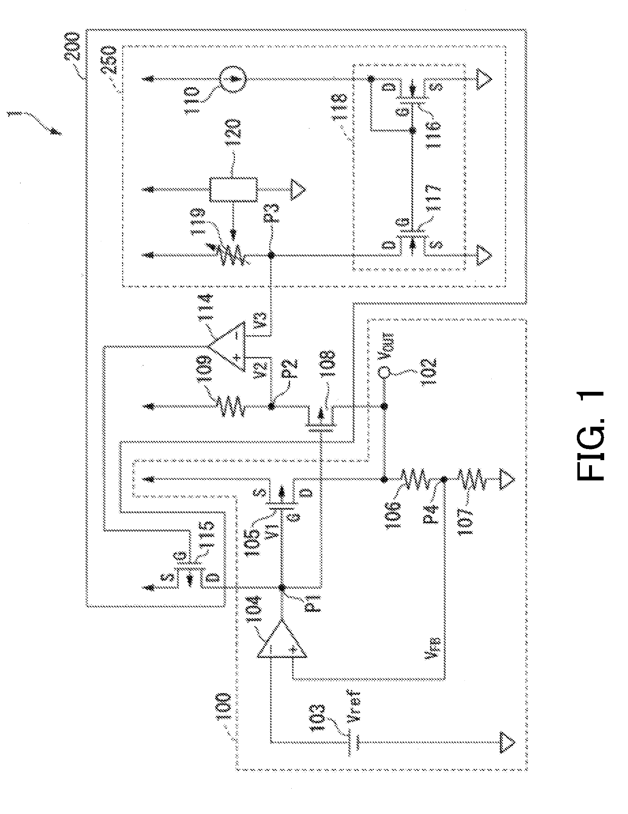
[0022]The first embodiment of the present invention will hereinafter be described with reference to the accompanying drawings. FIG. 1 is a schematic block diagram illustrating a voltage regulator which is one of a power supply circuit using an overcurrent limiting circuit according to the first embodiment of the present invention.

[0023]In the schematic block diagram, the voltage regulator 1 includes a voltage output circuit 100 and an overcurrent limiting circuit 200.

[0024]The voltage output circuit 100 outputs an output voltage Vout having a prescribed voltage set in advance from an output terminal 102. The voltage output circuit 100 has a reference voltage source 103, an error amplifier circuit 104, an output stage transistor 105, and resistors 106, 107.

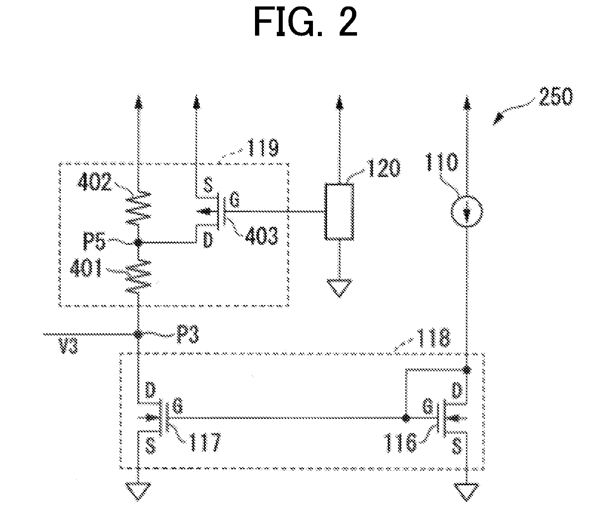
[0025]The overcurrent limiting circuit 200 has a current detection transistor 108, a resistor 109, an error amplifier circuit 114, a gate voltage adjustment transistor 115, and a limit voltage generation circuit 250.

[0026]The limit...

second embodiment

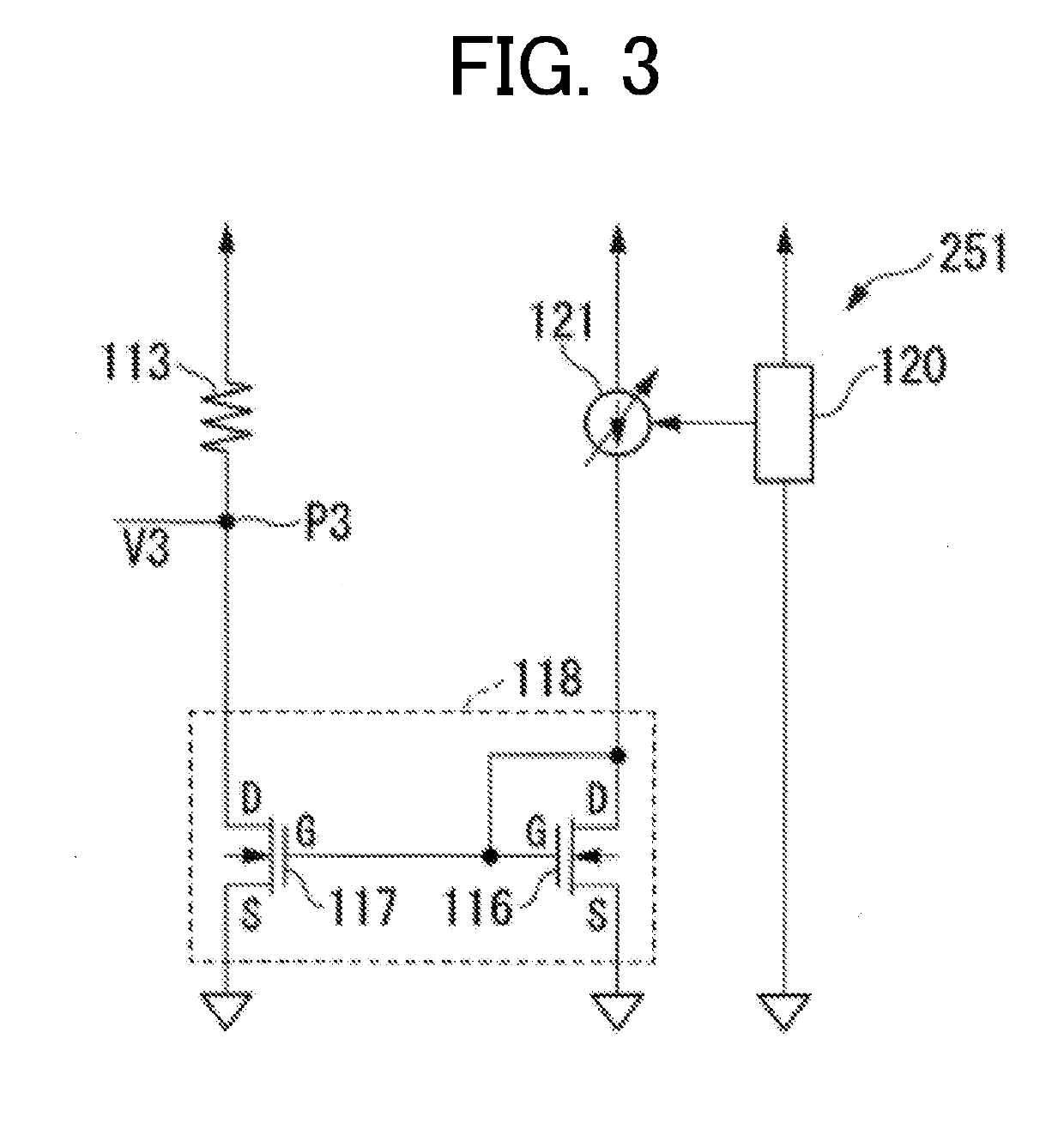
[0065]A second embodiment of the present invention will hereinafter be described with reference to the accompanying drawings. FIG. 3 is a schematic block diagram illustrating a limit voltage generation circuit in an overcurrent limiting circuit according to the second embodiment of the present invention.

[0066]The second embodiment includes a limit voltage generation circuit 251 instead of the limit voltage generation circuit 250 illustrated in FIG. 1. In other part of the configuration the second embodiment is similar to the first embodiment illustrated in FIG. 1.

[0067]The limit voltage generation circuit 251 includes a variable constant current source 121, a current mirror circuit 118, a resistor 113 being a current-voltage converter, and a limit voltage controller 120.

[0068]The variable constant current source 121 has one end connected to a power supply, the other end connected to a gate G and a drain D of a transistor 116 in the current mirror circuit 118, and a control terminal ...


PUM


Abstract

The overcurrent limiting circuit includes: a limit voltage generation circuit generating a limit voltage which defines the limit current value as a current corresponding to a magnitude of a power supply voltage; a source follower having an output terminal and an input terminal which is connected to a gate of the output stage transistor, and configured to supply from the output terminal a voltage level-shifted from a voltage provided to the input terminal; an error amplifier circuit amplifying a difference between the limit voltage and the voltage supplied from the source follower; and a gate voltage adjustment transistor having a gate to which the voltage supplied from the error amplifier circuit is applied, and controlling a gate voltage applied to the gate of the output stage transistor.

Description

RELATED APPLICATIONS[0001]This application claims priority under 35 U.S.C. § 119 to Japanese Patent Application No. 2018-018423 filed on Feb. 5, 2018, the entire content of which is hereby incorporated by reference.BACKGROUND OF THE INVENTION1. Field of the Invention[0002]The present invention relates to an overcurrent limiting circuit, an overcurrent limiting method, and a power supply circuit.2. Description of the Related Art[0003]A constant-voltage power supply circuit supplies a constant voltage stably even when an output current changes due to a load fluctuation or the like.[0004]However, when the load fluctuation is large and a current flows beyond the rated value, e.g., in a case of occurrence of a ground fault, etc., there is a need to prevent damage to the transistor at an output stage (hereinafter output stage transistor) of the power supply caused by heat which is generated by an overcurrent.[0005]The constant-voltage power supply circuit is thus required to have an overc...

Claims


Application Information

Patent Timeline
IPC IPC(8): G05F1/573G05F1/575
CPCG05F1/573G05F1/575H02M1/32G05F1/00H02M1/325G05F1/569
Inventor TOMIOKA, TSUTOMU
Owner ABLIC INC
Why Eureka
Try Eureka