
In-flight monitoring of aero engine health

a gas turbine engine and in-flight monitoring technology, which is applied in the direction of gas turbine engine testing, machines/engines, mechanical equipment, etc., can solve the problems of rapid decoupling between the turbine and its respective compressor, compressor may decelerate rapidly, and the turbine may accelerate rapidly

Active Publication Date: 2021-09-30
ROLLS ROYCE DEUT LTD & CO KG
View PDF10 Cites 5 Cited by
  • Summary
  • Abstract
  • Description
  • Claims
  • Application Information

AI Technical Summary

Benefits of technology

The patent describes a method for early detection of distress in the torque path by tracking the behavior of power delivery to the turbine through analysis of the torque path. This method can even detect low levels of twist in the torque path, potentially indicating unhealthy conditions. The technique involves measuring rotational speeds and calculating torsional vibrational characteristics, which can provide an indication of shaft system torque path performance. Overall, this method can improve the reliability and preventive maintenance of wind power systems.

Problems solved by technology

This breakage in the shaft leads to an instantaneous decoupling between the turbine and its respective compressor.
As a result the compressor may decelerate rapidly, as it is no longer being driven by the turbine, and the turbine may accelerate rapidly, as it no longer driving the compressor.
The rapid acceleration of the turbine is particularly concerning, as over-speed events can lead to disintegration of the turbine, including possibly bursting of the turbine disc, and further damage to the gas turbine engine.
In this way it is possible to discern excessive twist in the gearbox, which is a part of the shaft system that can be susceptible to wear due to its gear-mesh connections.

Method used


Image

  • In-flight monitoring of aero engine health
  • In-flight monitoring of aero engine health
  • In-flight monitoring of aero engine health

Examples


Embodiment Construction

[0053]Aspects and embodiments of the present disclosure will now be discussed with reference to the accompanying figures. Further aspects and embodiments will be apparent to those skilled in the art.

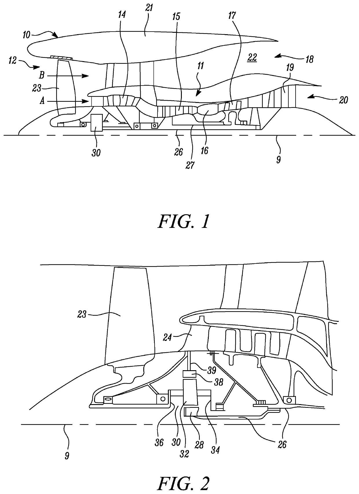
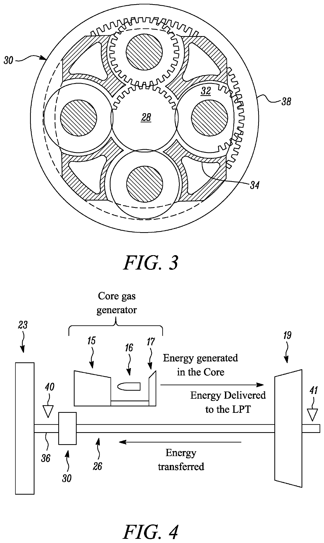
[0054]FIG. 1 illustrates a gas turbine engine 10 having a principal rotational axis 9. The engine 10 comprises an air intake 12 and a propulsive fan 23 that generates two airflows: a core airflow A and a bypass airflow B. The gas turbine engine 10 comprises a core 11 that receives the core airflow A. The engine core 11 comprises, in axial flow series, a low pressure compressor 14, a high-pressure compressor 15, combustion equipment 16, a high-pressure turbine 17, a low pressure turbine19 and a core exhaust nozzle 20. A nacelle 21 surrounds the gas turbine engine 10 and defines a bypass duct 22 and a bypass exhaust nozzle 18. The bypass airflow B flows through the bypass duct 22. The fan 23 is attached to and driven by the low pressure turbine 19 via a shaft 26 and an epicyclic gearbox 30...


PUM


Abstract

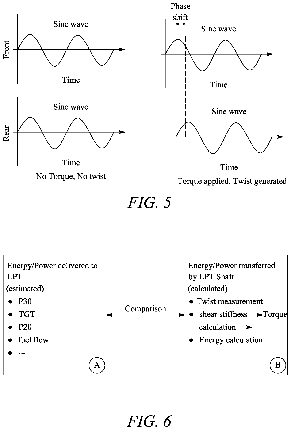
A method for in-flight monitoring of the health of an aero gas turbine engine including in flow series a compressor system, a core gas generator including a combustor, and a turbine, and further including a shaft system connecting the turbine to the compressor system and forming a torque path there between. The method includes: measuring a first rotational speed of a forward portion of the shaft system; measuring a second rotational speed of a rear portion of the shaft system; measuring other operational parameters of the engine; calculating from the measured rotational speeds the power delivered by the torque path from the turbine to the compressor system; calculating from the other measured operational parameters the power delivered to the turbine by the core gas generator; correlating the power delivered by the torque path at a given time with the power delivered to the turbine at that time.

Description

CROSS-REFERENCE TO RELATED APPLICATIONS[0001]This specification is based upon and claims the benefit of priority from UK Patent Application Number 2004668.6 filed on 31 Mar. 2020, the entire contents of which are incorporated herein by reference.BACKGROUNDField of the Disclosure[0002]The present disclosure relates to in-flight monitoring of the health of an aero gas turbine engine.Description of the Related Art[0003]Modern gas turbine engines typically have up to three compressor-turbine groups, also referred to as spools, connected by respective concentric shafts. These compressor-turbine groups are responsible for the compression and expansion of air passing through the engine.[0004]For example, the Rolls-Royce Trent 1000 aerospace gas turbine engine has three compressor-turbine groups: the low-pressure compressor-turbine group, the intermediate-pressure compressor-turbine group, and the high-pressure compressor-turbine group. Each of these has a corresponding compressor and turbi...

Claims


Application Information

Patent Timeline
Patent Type & Authority Applications(United States)
IPC IPC(8): F01D21/14F01D21/00F02C7/36
CPCF01D21/14F01D21/003F02C7/36F05D2220/323F05D2260/4031F05D2260/80F05D2270/301F05D2270/303F05D2270/304F05D2270/334F05D2270/335F05D2270/023F01D21/045F05D2240/60F05D2260/821Y02T50/60F01D21/04F02C7/00F02C9/00G01M15/14
Inventor CALDERON, JORGE
Owner ROLLS ROYCE DEUT LTD & CO KG
Learn More