Eureka AIR delivers breakthrough ideas for toughest innovation challenges, trusted by R&D personnel around the world.

Method, device and system for analyzing tunnel clearance based on laser point cloud

a laser point cloud and tunnel clearance technology, applied in surveying, height/levelling measurement, instruments, etc., can solve the problems of consuming a lot of manpower and material resources, further damage to the tunnel infrastructure, and low efficiency and accuracy, so as to accurately obtain the relative position relationship, the effect of quick determination of the intrusion situation and strong robustness

Inactive Publication Date: 2021-09-30
NANJING UNIV OF AERONAUTICS & ASTRONAUTICS
View PDF0 Cites 9 Cited by
  • Summary
  • Abstract
  • Description
  • Claims
  • Application Information

AI Technical Summary

Benefits of technology

This patent describes a method, device, and system for analyzing tunnel clearance based on a laser point cloud. The method has the following technical effects: 1) The mobile scanning does not need to be strictly perpendicular to the tunnel axis, making the method more robust against data noise. 2) After extracting point cloud subsets of rails, a base line of the tunnel clearance is constructed, and the point cloud of the tunnel section is registered with the point cloud of the tunnel clearance based on constraint conditions. This allows the method to accurately determine the relation between the tunnel clearance and the section of the tunnel, quickly identifying any potential intrusion. Overall, this patent provides a reliable and automated solution for inspecting and calculating the clearance intrusion problem in subway tunnels, reducing the risk of train operation and improving safety.

Problems solved by technology

Since the tunnel segments have greater rigidity, when the cylindrical tunnels deform, the tension and compression are exerted at joints of the segments, resulting in fragmentation at both ends of the segments and failure of waterstop, which will further damage the tunnel infrastructure.
Generally, tunnels are manually and visually inspected, which has low efficiency and accuracy, and consumes a lot of manpower and material resources.
However, the discrete data obtained by the traditional total station measurement has low data integrity and low precision, and subsequent data processing is difficult.
Thus, the subway deformation information and tunnel clearance analysis results cannot be directly obtained through the point cloud data of the scanned subway tunnel, and pre-processing and post-analysis are required for the scanned data.
In addition, a expensive inspection device should be built to improve the accuracy of the point cloud data.
However, a large amount of sample data is required for the regression model, and the calculation process is complicated.
In addition, different models should be recreated for tunnels of different structures, and the method has low accuracy and efficiency.
Thus, it cannot meet the requirements of modern tunnel inspection and monitoring.
There is no method to determine whether the tunnel section intrudes the tunnel clearance.

Method used


Image

  • Method, device and system for analyzing tunnel clearance based on laser point cloud
  • Method, device and system for analyzing tunnel clearance based on laser point cloud
  • Method, device and system for analyzing tunnel clearance based on laser point cloud

Examples


embodiment 1

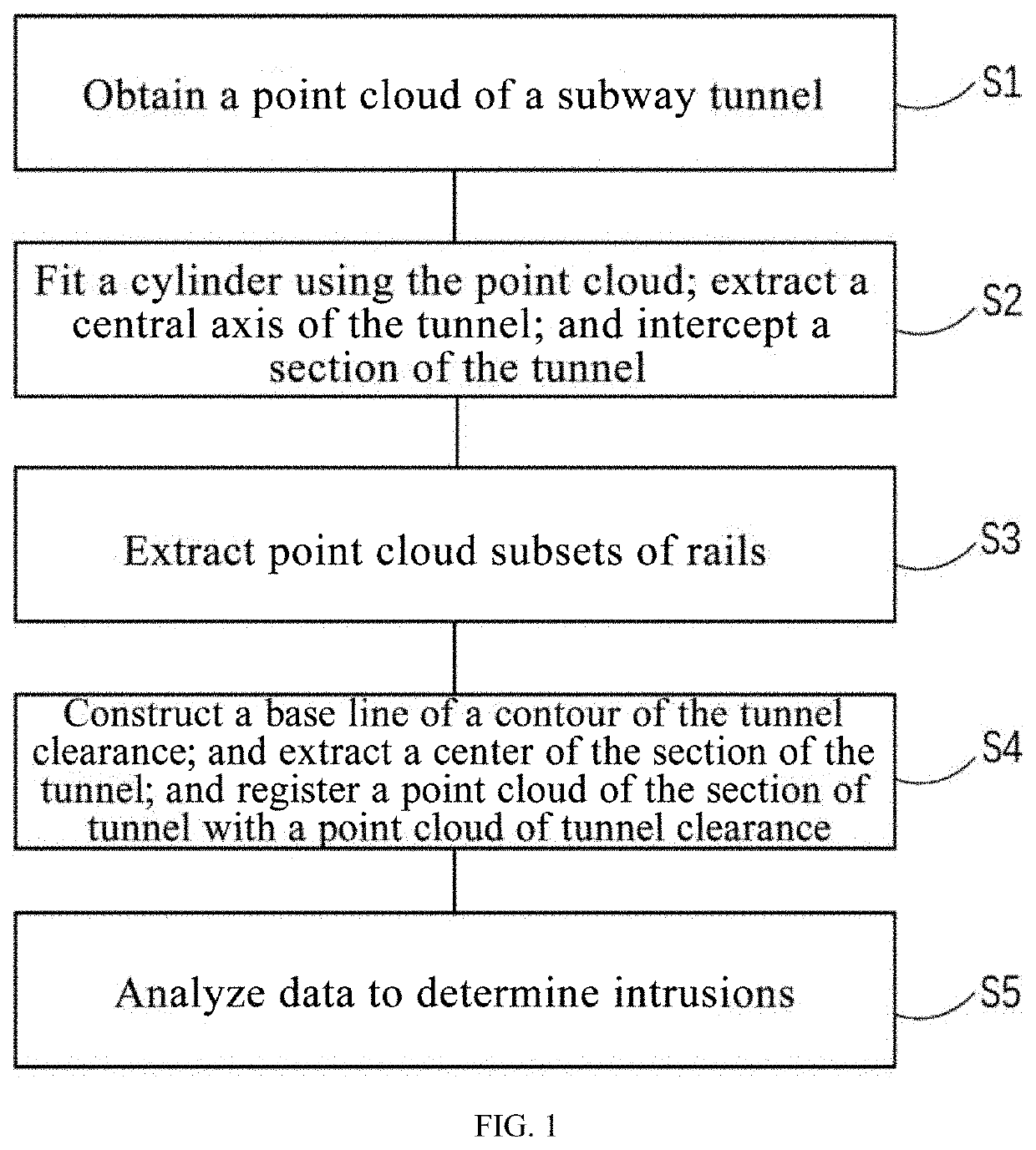
[0062]This embodiment illustrates a method for analyzing tunnel clearance based on laser point clouds, which can be directly applied to various laser point clouds based clearance analysis devices of subway tunnels. In specific implementation, the application can be realized by writing corresponding programs in controllers of clearance analysis device of the subway tunnel. As shown in FIG. 1, the method includes the following steps.

[0063]1) A point cloud of a subway tunnel is obtained. Specifically, the tunnel is scanned by a three-dimensional scanner based tunnel inspection vehicle to obtain the point cloud of the subway tunnel.

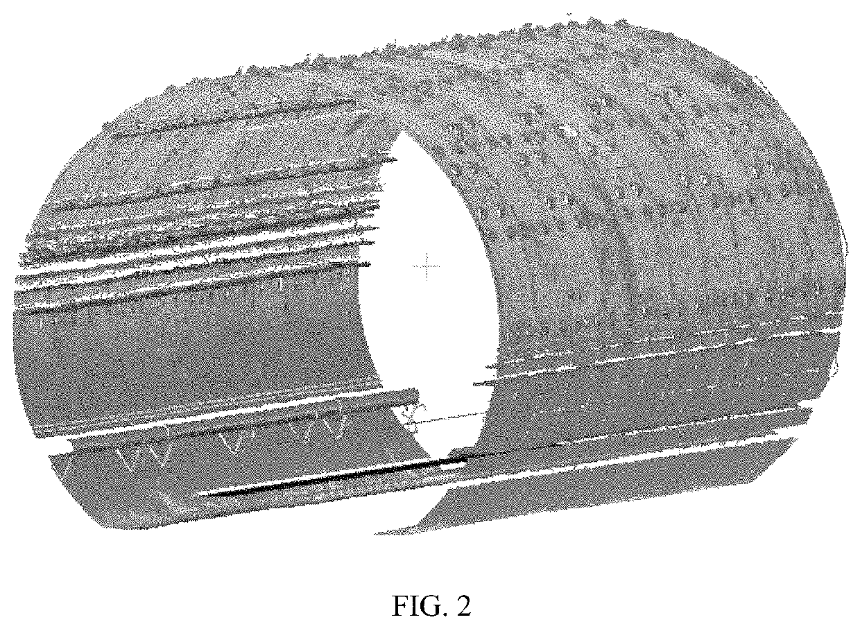
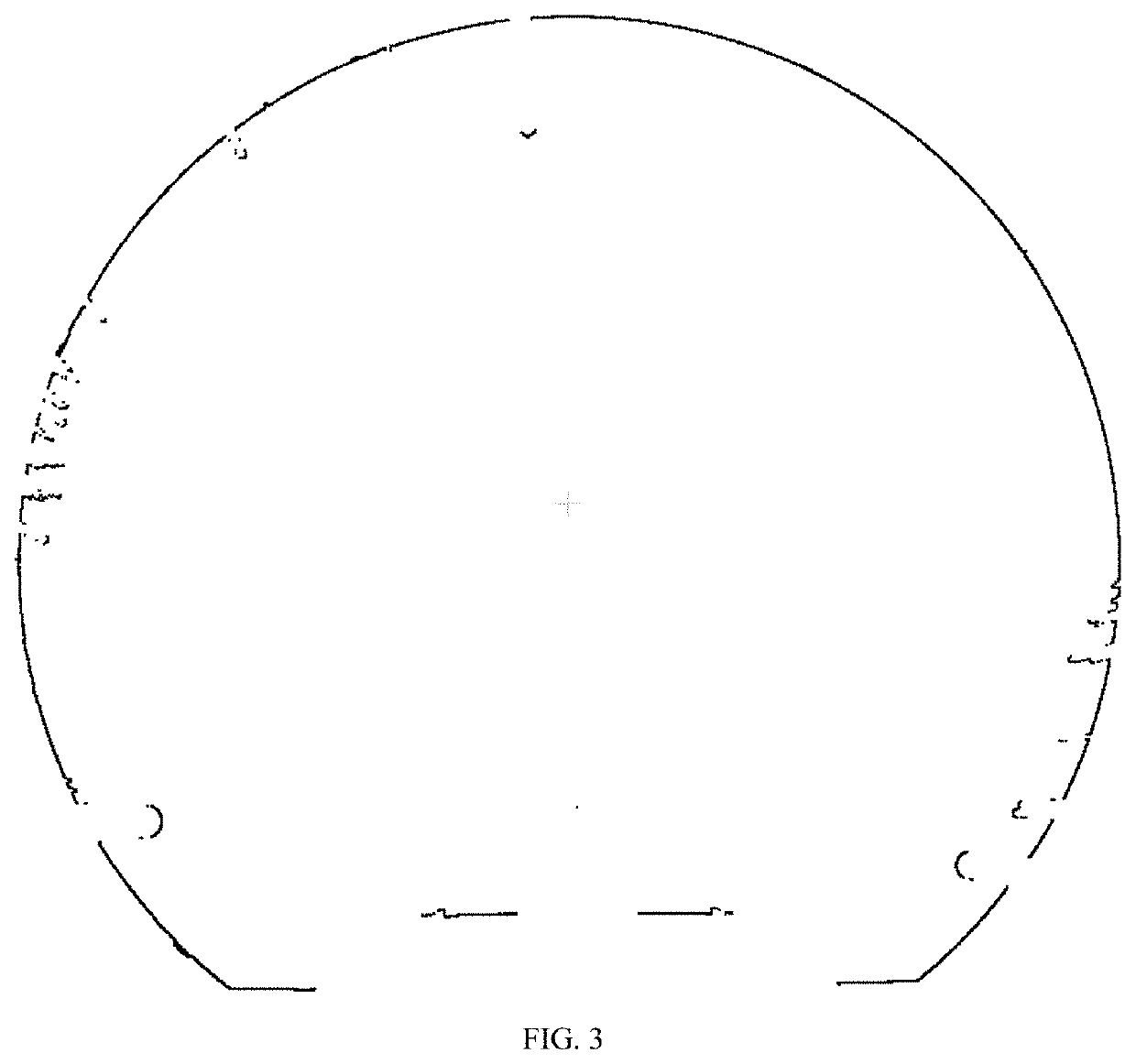
[0064]2) A cylinder is fitted using the point cloud of the tunnel. A central axis of the tunnel is extracted. A section of the tunnel is intercepted based on the central axis of the tunnel. Specifically, the cylinder is fitted using the point cloud through Gaussian mapping. The central axis of the subway tunnel is extracted, and the point cloud data of a sing...

embodiment 2

[0073]Based on the method for analyzing tunnel clearance based on the laser point cloud, this embodiment provides a device for analyzing tunnel clearance based on a laser point cloud. Specifically, FIG. 2 shows an optional structural diagram of the device. As shown in FIG. 5, the device includes a data acquisition module, a preprocessing module, and an analysis module.

[0074]The data acquisition module is configured to acquire 3D point cloud data of a subway tunnel. The subway tunnel is scanned through a tunnel detection vehicle based 3D laser scanner system, and 3D point cloud data of the subway tunnel is exported for subsequent preprocessing and analysis calculation.

[0075]The preprocessing module is connected to the data acquisition module, and is configured to pre-process the point cloud data of the subway tunnel, intercept the segment, and extract the central axis of the tunnel and the point cloud subsets of rails. The preprocessing module includes an interception unit and an ext...


PUM


Abstract

A point cloud of a tunnel is obtained. A cylinder is fitted using the point cloud of the tunnel. A central axis of the tunnel is extracted. A section of the tunnel is intercepted based on the central axis of the tunnel. Point cloud subsets of two rails are extracted. A base line of a contour of the tunnel clearance is constructed. A center of the section of the tunnel is extracted. A point cloud of the section of the tunnel is registered with a point cloud of the tunnel clearance based on a constraint condition. The point cloud of the section of the tunnel and the point cloud of the tunnel clearance which are registered with each other are analyzed to determine whether the tunnel clearance is intruded.

Description

CROSS-REFERENCE TO RELATED APPLICATIONS[0001]This application claims the benefit of priority from Chinese Patent Application No. 202010218307.4, filed on Mar. 25, 2020. The content of the aforementioned application, including any intervening amendments thereto, is incorporated herein by reference in its entirety.TECHNICAL FIELD[0002]The present application relates to tunnel clearance analysis, in particular to a method, a device and a system for analyzing tunnel clearance based on a laser point cloud.BACKGROUND[0003]As the rail transit technology rapidly develops, infrastructures of subway tunnels built many years ago are required to be maintained. The newly built subway tunnels may be subjected to deformation due to comprehensive factors, such as geology, groundwater, construction of adjacent foundation pits, and its structural load. This has an inverse impact on the safety of the tunnel and the operation of the trains. Therefore, deformation monitoring must be carried out in a tim...

Claims


Application Information

Patent Timeline
Patent Type & Authority Applications(United States)
IPC IPC(8): G01C5/00G01C7/06
CPCG01C5/00G01C7/06G01C15/002G01S17/89
Inventor WANG, JUNWU, YUXIANGLU, DENING
Owner NANJING UNIV OF AERONAUTICS & ASTRONAUTICS
Why Eureka
Eureka Blog
Learn More