
Project management systems and methods incorporating proximity-based association

a project management system and proximity-based association technology, applied in soil shifting machines/dredgers, instruments, data processing applications, etc., can solve the problems of lack of clear oversight of mass hauling and payload activities of a plurality of separate but collaborating machines, difficult to track material movement, and difficulty in determining and keeping a record of what material was loaded by which operator, etc., to increase the productivity of the fleet of machines and reduce the idle period of machines

Pending Publication Date: 2021-09-30
FINNING INT
View PDF3 Cites 1 Cited by
  • Summary
  • Abstract
  • Description
  • Claims
  • Application Information

AI Technical Summary

Benefits of technology

The patent text describes a system where data from a fleet of machines is analyzed to track material movement. Based on this data, a plan is created to decide which machines should be used and where they should be sent to increase productivity and reduce idle periods. Commands are then generated from this plan and sent to each machine. The technical effect of this system is more efficient use of machines and improved productivity.

Problems solved by technology

In general, however, tracking material movement is difficult when there are multiple separate machines collaborating for the earthmoving and earthworks operations.
While information concerning a machine's haul and cycle times can be obtained from data provided by load sensors and other on-board digital systems, the limitations of using disparate data sets originating from separate machines make it difficult to determine and keep a record of what material was loaded by what operator, what truck it was loaded into, and where the material was ultimately dumped.
As such, there is a lack of clear oversight over mass hauling and payload activities by a plurality of separate but collaborating machines.

Method used


Image

  • Project management systems and methods incorporating proximity-based association
  • Project management systems and methods incorporating proximity-based association
  • Project management systems and methods incorporating proximity-based association

Examples


Embodiment Construction

[0018]The description which follows, and the embodiments described therein, are provided by way of illustration of examples of particular embodiments of the principles of the present invention. These examples are provided for the purposes of explanation, and not limitation, of those principles and of the invention.

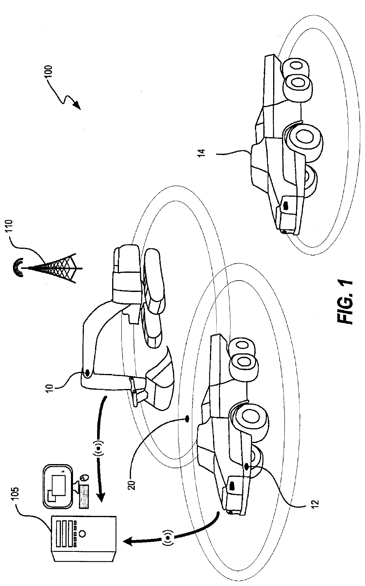
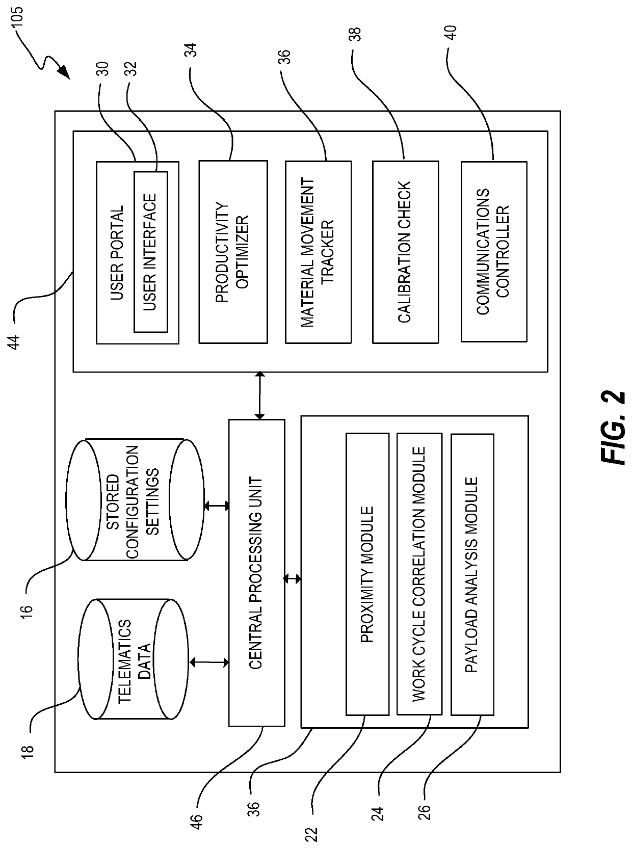
[0019]The disclosure herein relates to project management systems and methods for tracking material movement by multiple independent earthmoving machines. Particular embodiments provide systems and methods for correlating work cycles and analysing payloads of collaborating machines and identifying associations between collaborating machines, through an automated process that is based at least in part on positional and temporal proximity. The identification of associated machines and results of the correlation can be used for productivity analysis. Systems and methods described herein have particular applications for improving and / or optimizing the productivity of a fleet o...


PUM


Abstract

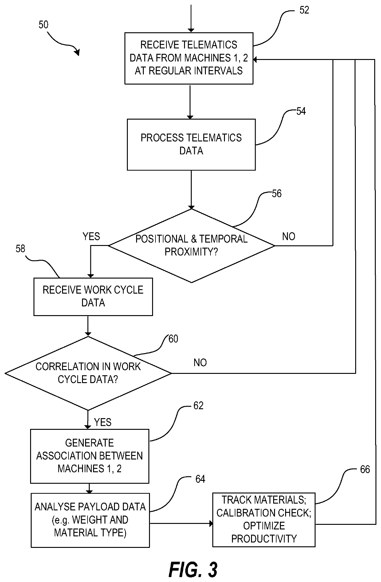
Systems and methods are disclosed for management of a fleet of machines operating in a construction and / or civil engineering project. Telematics data is received from first and second machines at regular intervals. Positional and temporal proximity is determined between the first and second machines based at least in part on an analysis of the telematics data, indicating for example that the first machine is within a predetermined maximum distance of the second machine for at least a predetermined minimum duration. If there is positional and temporal proximity, work cycle data is received from the machines and is correlated. If there is a correlation in the work cycle data, an association is generated between the first and second machines and the association is applied to enable inheritance of material type between the first and second machines to support automated mass haul monitoring, and generate and implement a construction plan.

Description

RELATED APPLICATIONS[0001]This application claims priority from U.S. Provisional Patent Application No. 62 / 754,138 filed Nov. 1, 2018 entitled “Project Management Systems and Methods Incorporating Proximity-Based Association”. For the purposes of the United States, this application claims the benefit under 35 USC § 119 of U.S. Provisional Patent Application No. 62 / 754,138 filed Nov. 1, 2018 entitled “Project Management Systems and Methods Incorporating Proximity-Based Association”, which is incorporated herein by reference in its entirety.TECHNICAL FIELD[0002]This present disclosure relates generally to project management systems and methods for managing large construction and civil engineering projects.BACKGROUND[0003]Infrastructure construction and civil engineering projects typically involve significant earthmoving and earthworks operations. These operations require coordination of the activities of multiple independent machines, such as loaders (e.g. excavators, wheel loaders, e...

Claims


Application Information

Patent Timeline
IPC IPC(8): G06Q10/06G07C5/08E02F9/20G06Q50/08
CPCG06Q10/063114G06Q10/06313G06Q50/08E02F9/2054E02F9/205G07C5/0808G06Q10/0631G06Q10/0639G07C5/008
Inventor SARKARIA, SARBJITWILLMS, JORDANBLAKE, ANTHONY VINCENT
Owner FINNING INT
Learn More