Battery pack

a battery pack and battery technology, applied in the field of batteries, can solve the problems of increasing the heat transmission to such electronic components, affecting the performance of electronic components, etc., and achieve the effect of reducing the size of the board and the number of parts on the board

Active Publication Date: 2021-09-30
MAKITA CORP
View PDF2 Cites 8 Cited by
  • Summary
  • Abstract
  • Description
  • Claims
  • Application Information

AI Technical Summary

Benefits of technology

[0011]In addition, the busbar may comprise a shunt resistor. If the busbar comprises the shunt resis

Problems solved by technology

If the current-carrying capacity is increased, then there is a possibility that the amount of heat transmitted to such electronic components will inc

Method used


Image

  • Battery pack
  • Battery pack
  • Battery pack

Examples


Embodiment Construction

[0021]Embodiments (modes) for carrying out aspects of the present teachings are explained below, with reference to the drawings.

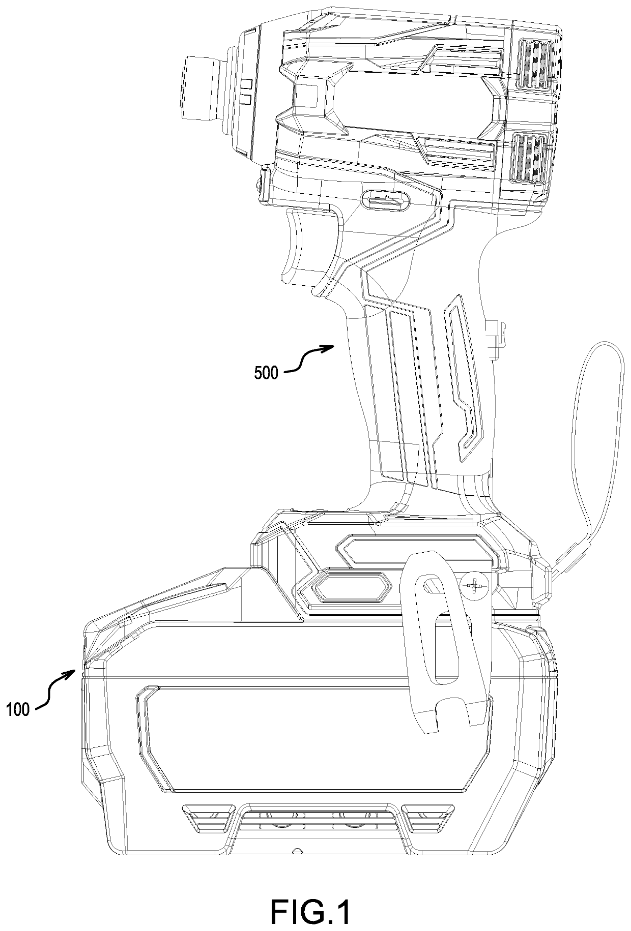
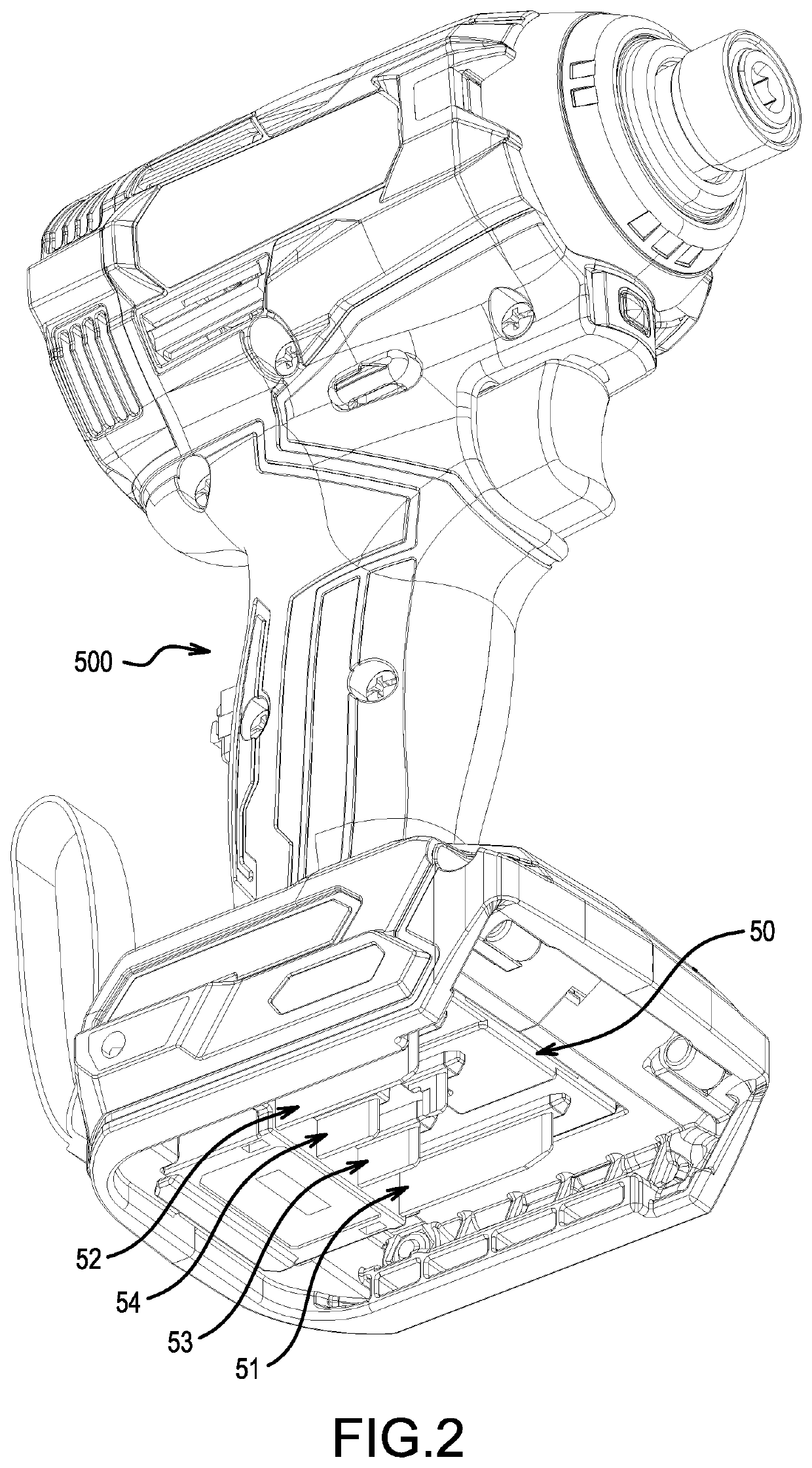
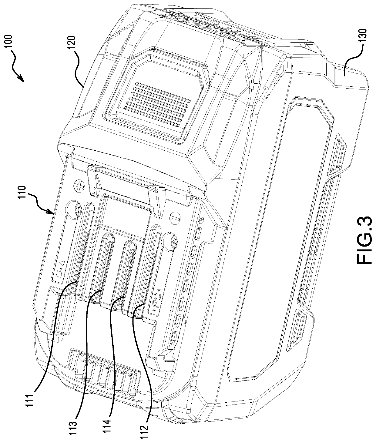
[0022]First, the configuration of a battery system according to a first representative, non-limiting embodiment of the present teachings will be explained, with reference to FIGS. 1-3. The battery system according to the present (first) embodiment comprises a battery pack (battery cartridge) 100 and an electric work machine 500, such as a power tool or outdoor power equipment. The battery pack 100 supplies electric power (current) to the electric work machine 500. The electric work machine 500 becomes operable upon being connected to a supply of electric power (current) from the battery pack 100.

[0023]In the present embodiment, the electric work machine 500 is an impact driver, but electric work machines 500 according to the present teachings are not limited to an impact driver. That is, the type of electric work machine 500 is not particularly limited as l...


PUM


Abstract

A battery pack may include a battery (60), a board (10), a first connection terminal (12), a second connection terminal (11), a control circuit (620), and a busbar (18). The first connection terminal is provided on the board and is configured to be connected to an electric work machine (500). The second connection terminal is provided on the board and is connected to the battery. The control circuit is provided on the board and is configured to control discharging of the battery. The busbar is provided on the board in a current discharge path between the first connection terminal and the second connection terminal.

Description

CROSS-REFERENCE TO RELATED APPLICATION[0001]The present application claims priority to Japanese patent application No. 2020-054847 filed on Mar. 25, 2020, the contents of which are hereby fully incorporated herein by reference.TECHNICAL FIELD[0002]The present disclosure relates to a battery pack, e.g., for usage with cordless power tools and outdoor power equipment.BACKGROUND ART[0003]US 2014 / 0375231 discloses a battery pack that comprises a multilayer board, on which a microcontroller, a discharge terminal, a charging terminal, a negative-electrode terminal, etc. are installed. By connecting the negative-electrode terminal to a negative-electrode of a battery cell using a multilayer semiconductor pattern, the current-carrying capacity of the above-mentioned battery pack can be increased.SUMMARY OF THE INVENTION[0004]When electric current flows through the negative-electrode terminal and the multilayer semiconductor pattern, the negative-electrode terminal and the multilayer semicon...

Claims


Application Information

Patent Timeline
IPC IPC(8): H01M50/519H01M10/46H01M10/655H01M10/653H01M50/522H01M10/42H01M10/6235
CPCH01M50/519H01M10/46H01M10/655H02J7/0042H01M50/522H01M10/4257H01M10/6235H01M10/653H02J7/00302H02J7/00306H02J7/00309H02J7/0014H02J7/00714H02J7/007182H02J7/007192H05K7/2039H02J7/0025H02J7/0063H01M50/247H01M2220/30H01M50/296H01M10/425H01M50/284H01M2010/4271H01M10/48H01M10/486H01M2200/00H01M50/204H01M50/242Y02E60/10H02J7/0047H02J7/007194
Inventor GYODA, MINORU
Owner MAKITA CORP
Why Eureka
Try Eureka