Sheet feeding device and image forming apparatus

a technology of forming apparatus and feeding device, which is applied in the direction of transportation and packaging, thin material processing, and article separation, etc., can solve the problems of increasing the distancing position between the conveying tray and the pickup roller, and achieve the effect of reducing the distancing position variation

Active Publication Date: 2021-10-07
CANON KK
View PDF2 Cites 0 Cited by
  • Summary
  • Abstract
  • Description
  • Claims
  • Application Information

AI Technical Summary

Benefits of technology

[0011]As described above, according to the present invention, variance in distancing positions can be reduced, with...

Problems solved by technology

However, the above-described conventional examples have a problem in that varianc...

Method used


Image

  • Sheet feeding device and image forming apparatus
  • Sheet feeding device and image forming apparatus
  • Sheet feeding device and image forming apparatus

Examples


first embodiment

Overall Configuration

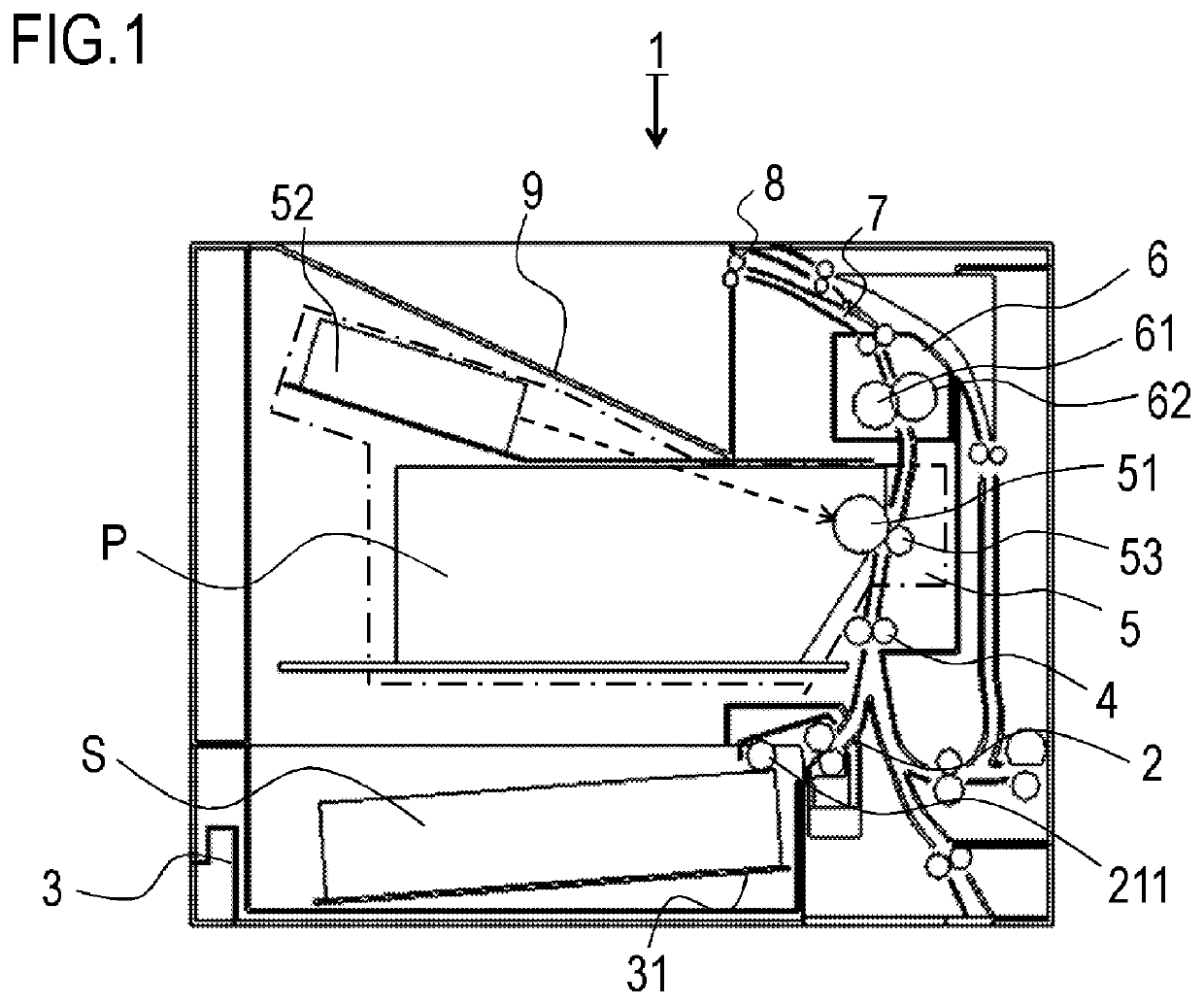
[0035]FIG. 1 is a schematic cross-sectional view illustrating an overall configuration of an image forming apparatus and a sheet feed device. The image forming apparatus 1 forms images by an electrophotographic recording process, in which sheets (recording material) S are conveyed to an image forming portion, toner images are transferred thereupon, the sheets S are conveyed to a fixing portion where the toner images are fixed, and thereafter discharged to a discharge portion.

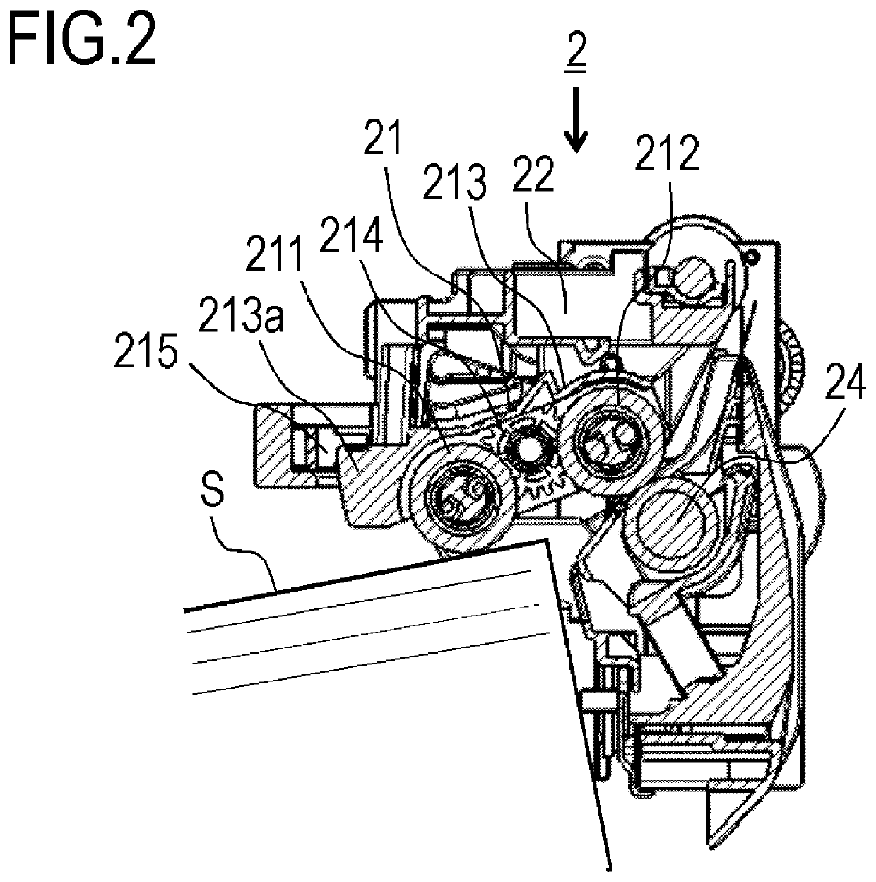
[0036]The sheets S are stored loaded in a cassette unit 3 serving as a sheet loading portion, which is loaded at a lower portion of the apparatus. The sheets S are fed out in order from the topmost sheet, by a feed roller 211 that rotates in a counterclockwise direction and that is provided in a feed unit 2 for feeding sheets S onto a sheet conveyance path of the apparatus main unit of the image forming apparatus 1, toward an image forming portion 5. The sheets S are sent to the image formin...

second embodiment

[0078]Next, a second embodiment of the present invention will be described with reference to FIGS. 13A and 13B through FIGS. 21A and 21B. Note that the present embodiment differs from the first embodiment with regard to the linking configuration of a feed roller contacting / distancing portion. Also, parts in the present embodiment that have the same configuration and function as those in the first embodiment are denoted with the same reference signs as in the first embodiment, and repetitive description will be omitted.

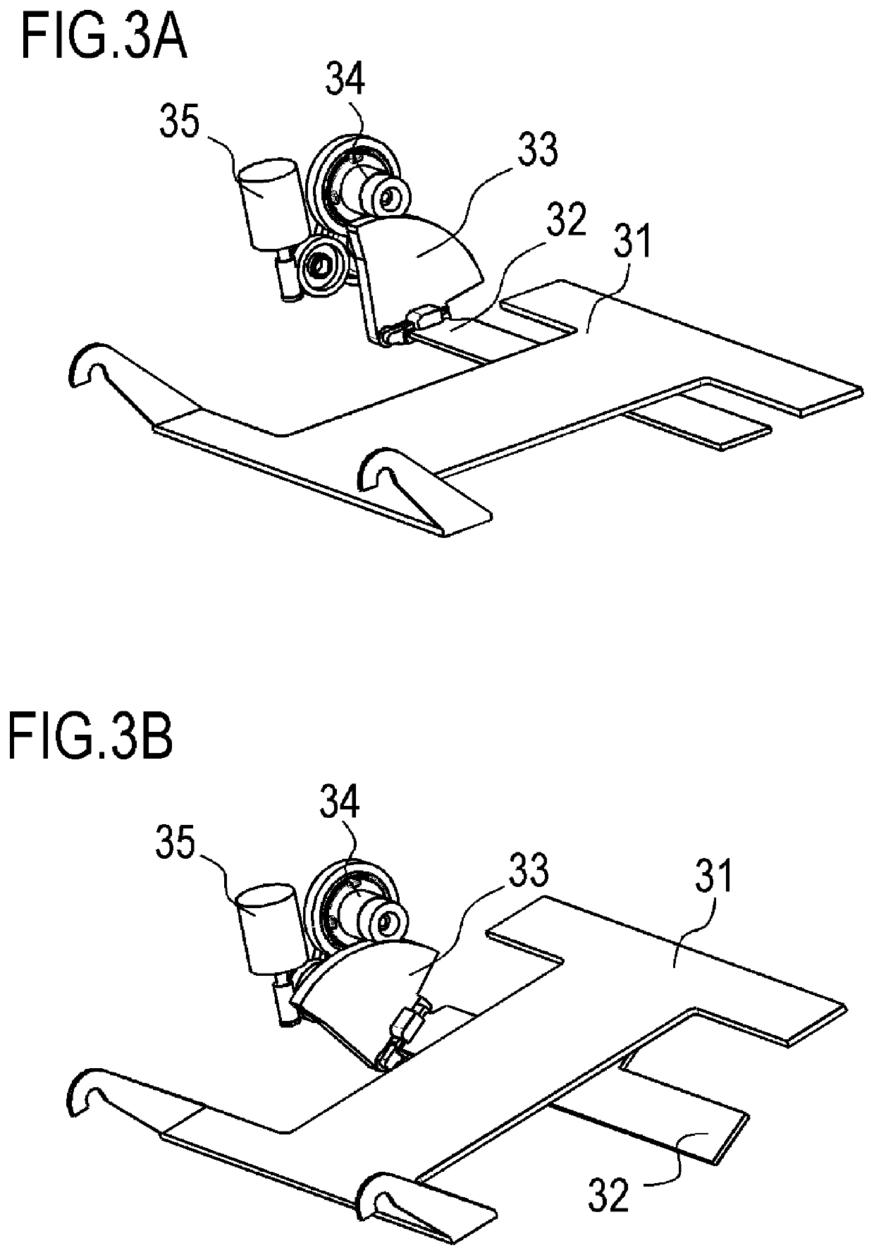
[0079]First, the overall configuration will be described with reference to FIGS. 13A and 13B. FIGS. 13A and 13B represent a linking configuration of the feed roller contacting / distancing portion. FIG. 13A is a perspective view of the feed roller contacting / distancing portion from the upstream side in the conveying direction, and FIG. 13B is a perspective view of the feed roller contacting / distancing portion from the downstream side in the conveying direction.

[0080]The ...


PUM


Abstract

A sheet feeding device includes a sheet loading portion which is capable of an elevating operations, and on which a sheet is loaded, a feeding member for feeding the sheet loaded on the sheet loading portion, the feeding member being capable of elevating movement between a contacting position in contact with the sheet, and a distanced position distanced upward from the sheet, and a control portion that controls the elevating operation of the sheet loading portion and the elevating movement of the feeding member. When the feeding member at the contacting position moves to the distanced position, the feeding member is distanced upward from the sheet loaded on the sheet loading portion after the sheet loading portion starts a descending operation.

Description

BACKGROUND OF THE INVENTIONField of the Invention[0001]The present invention relates to an image forming apparatus such as a photocopier, a printer, or the like, and to a sheet feeding device provided thereto.Description of the Related Art[0002]In general, conventional image forming apparatuses such as printers, photocopiers, and so forth, have a configuration provided with a sheet feeding unit for automatically feeding sheets toward an image forming portion that forms images on sheets, and a sheet loading tray that accommodates sheets and that is provided so as to be capable of elevating. Sheet feed units used in such image forming apparatuses are each provided with a pickup roller for feeding a topmost sheet, loaded on the sheet loading tray, to the image forming portion, and a separating portion for separating sheets, fed out from the pickup roller, into individual sheets. The sheet loading tray is provided with a sheet storage portion for storing sheets, and can store up to a ce...

Claims


Application Information

Patent Timeline
IPC IPC(8): B65H1/08B65H7/20
CPCB65H1/08B65H7/20B65H1/14B65H3/0684B65H3/0669B65H2801/06B65H7/02B65H2511/20B65H2511/22B65H2511/417B65H2511/414B65H3/06B65H3/0607B65H7/18B65H1/025
Inventor FUKADA, ICHIRO
Owner CANON KK
Why Eureka
Try Eureka