Optical to acoustic communications systems and methods

a communication system and acoustic technology, applied in the field of optical to acoustic communication systems and methods, can solve the problems of difficult communication between aircraft or satellites and submarines or other submerged devices, large antennas, and limitations, and achieve the effect of facilitating propagate through free spa

Active Publication Date: 2021-10-07
RAYTHEON CO
View PDF0 Cites 10 Cited by
  • Summary
  • Abstract
  • Description
  • Claims
  • Application Information

AI Technical Summary

Benefits of technology

[0003]Aspects and embodiments provide improved systems and methods for establishing communications links between an underwater object and an airborne or space-based object based on a combined acoustic and optical approach, which uses water surface tension to convert between the two communications mediums. Aspects and embodiments take advantage of the ability of light (optical signals) to propagate easily through free space and the ability of sound (acoustic signals) to propagate through water. As discussed in more detail below, aspects and embodiments use the nearly infinite impedance mismatch at the boundary between the water surface and air as a natural transducer to convert optical energy into acoustic energy for the purpose of communications. Additionally, certain embodiments include a mechanism for correcting for waveform perturbations introduced by sea state action, as discussed further below.

Problems solved by technology

Communications between an aircraft or satellite and submarines or other submerged devices is very difficult.
Several techniques exist for closing this link, but all have limitations.
This method, however, requires very large antennas, high power and has very low data rates.

Method used


Image

  • Optical to acoustic communications systems and methods
  • Optical to acoustic communications systems and methods

Examples


Embodiment Construction

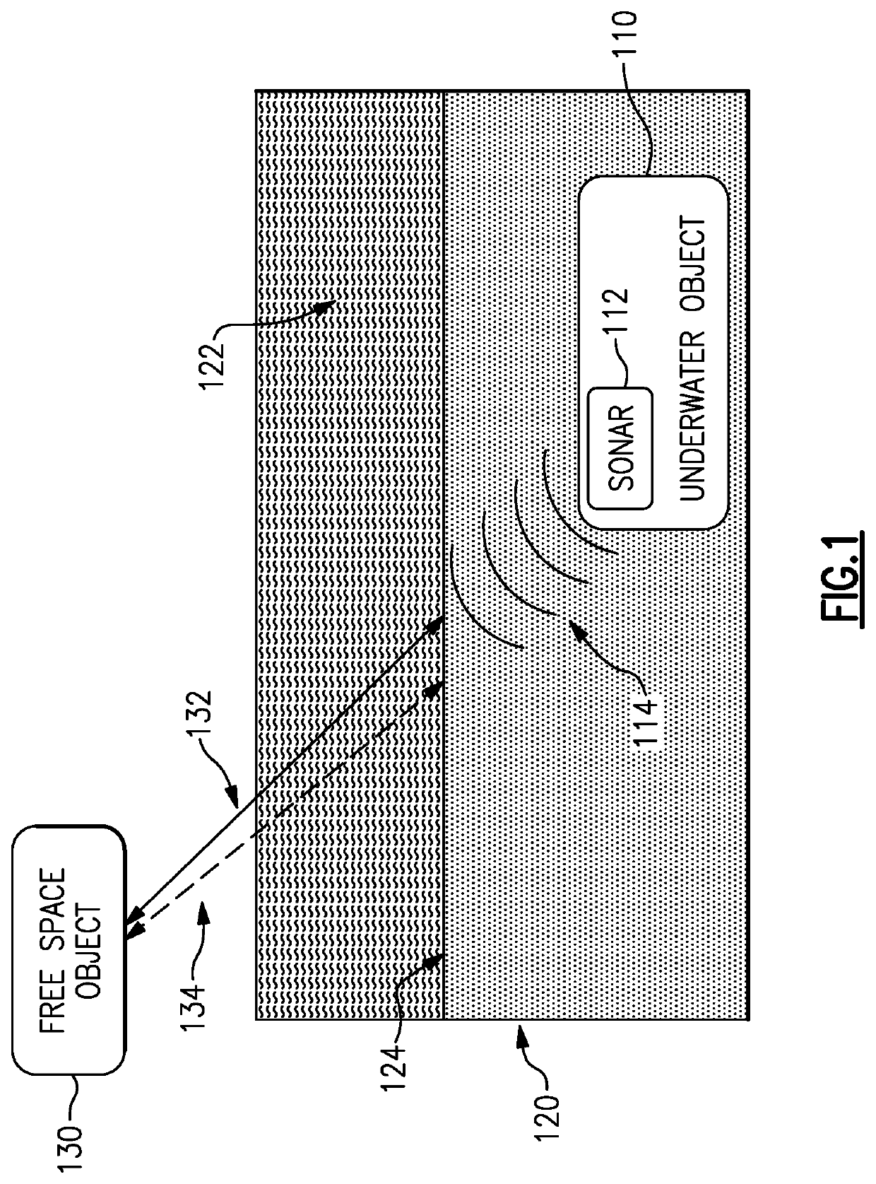
[0016]Aspect and embodiments are directed to a combined acoustic-optical communications method and system that can be used to establish a communications link between an underwater object, such as a submarine, and an object that transmits and receives optical signals through free space, such as a ship, an aircraft, or a satellite, for example (referred to herein as a “airborne platform”). In particular, aspects and embodiments provide an improved method for communicating information from the airborne platform to the submarine that leverages properties of the air-water boundary, as discussed in more detail below.

[0017]FIG. 1 is a block diagram of one example of such a communications system according to certain embodiments. Referring to FIG. 1, an underwater object 110 (generally referred to below as a submarine) is submerged in a body of water 120, such as an ocean. Communication is desired between the submarine 110 and an airborne platform 130. According to certain embodiments, a dat...


PUM


Abstract

Methods and apparatus for air to underwater communications. In one example, an optical transceiver configurable between two operational modes includes a laser assembly configured to transmit a modulated laser beam when in a first mode of the two operational modes and to transmit an unmodulated beam when in a second mode of the two operational modes, an optical receiver configured to receiver reflections of the unmodulated laser beam from a surface of a body of water and to output measurement data based on the reflections of the unmodulated laser beam, and a controller configured to determine surface conditions of the surface of the body of water based on the measurement data, to adjust at least one property of the modulated laser beam based on the surface conditions, and to operably switch the laser assembly between the first and second modes.

Description

CROSS-REFERENCE TO RELATED APPLICATIONS[0001]This application claims priority under 35 USC § 119(e) to U.S. Provisional Patent Application Ser. No. 62 / 927,345, titled “OPTICAL TO ACOUSTIC COMMUNICATIONS SYSTEMS AND METHODS,” filed Oct. 29, 2019, which is incorporated by reference herein in its entirety for all purposes.BACKGROUND[0002]Communications between an aircraft or satellite and submarines or other submerged devices is very difficult. Several techniques exist for closing this link, but all have limitations. For example, a common method of communicating from free space to an underwater vehicle is to use low frequency radio frequency communication. This method, however, requires very large antennas, high power and has very low data rates.SUMMARY OF INVENTION[0003]Aspects and embodiments provide improved systems and methods for establishing communications links between an underwater object and an airborne or space-based object based on a combined acoustic and optical approach, w...

Claims


Application Information

Patent Timeline
Patent Type & Authority Applications(United States)
IPC IPC(8): H04B13/02G01S7/486H04B10/50H04B10/118H04B10/80G01S15/08
CPCH04B13/02G01S7/486H04B10/503G01S2201/07H04B10/807G01S15/08H04B10/118G01S15/88G01S7/006G01S17/88H04B11/00
Inventor GRACEFFO, GARY M.KOWALEVICZ, ANDREWDOLGIN, BENJAMIN P.
Owner RAYTHEON CO
Why Eureka
Try Eureka