Light-emitting assembly with micro hydraulic power generator

Active Publication Date: 2021-10-14
PPI XIAMEN IND
View PDF0 Cites 0 Cited by
  • Summary
  • Abstract
  • Description
  • Claims
  • Application Information

AI Technical Summary

Benefits of technology

[0014]The above design can increase the area of impacting on the impeller by the water flow. Under the premise of the same water pressure, the rotation speed of this type of impeller improves the power generation efficiency of the coil module due to its different arrangement of the blades from those in the conventional technology.
[0015]Further, a temperature sensor is additionally provided in the power generation module, the transparent lampshade is provided with a through hole, and an electrical connection end of the temperature sensor is disposed in the transparent lampshade in a watertightl

Problems solved by technology

However, in the process of practical use, it is necessary to activate certain lighting effects (lighting or visual effects) while water is being used in some scenes; or because it is not easy to control the temperature of the hot water, in the process of water output, especially when the water outlet device is just turned on, the hot water that flows out suddenly may scald the user, and it needs to have the water temperature indicated.
However, in the conventional technology, to meet these design requirements, it is required to additionally design circuits, and in particular a special po

Method used


Image

  • Light-emitting assembly with micro hydraulic power generator
  • Light-emitting assembly with micro hydraulic power generator
  • Light-emitting assembly with micro hydraulic power generator

Examples


Embodiment Construction

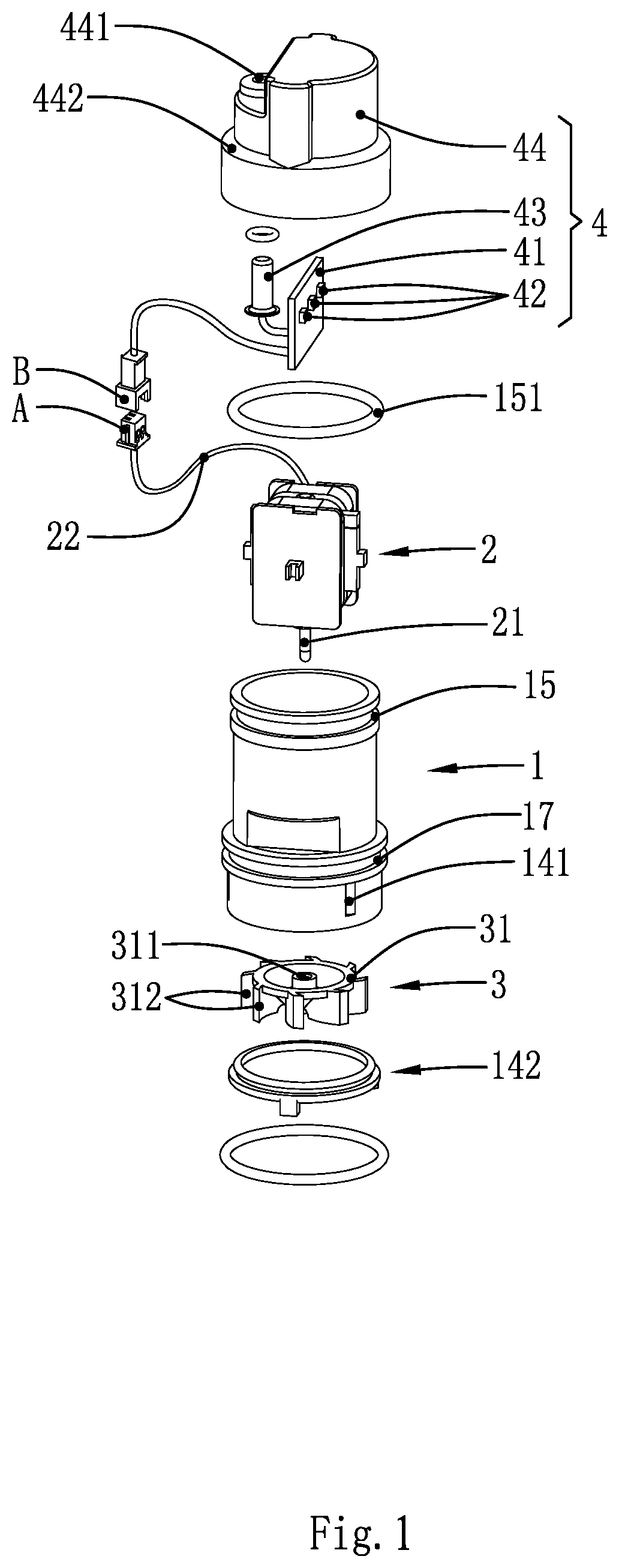
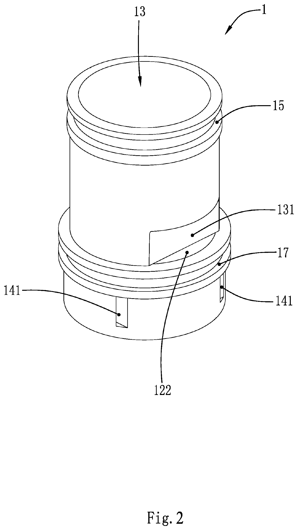
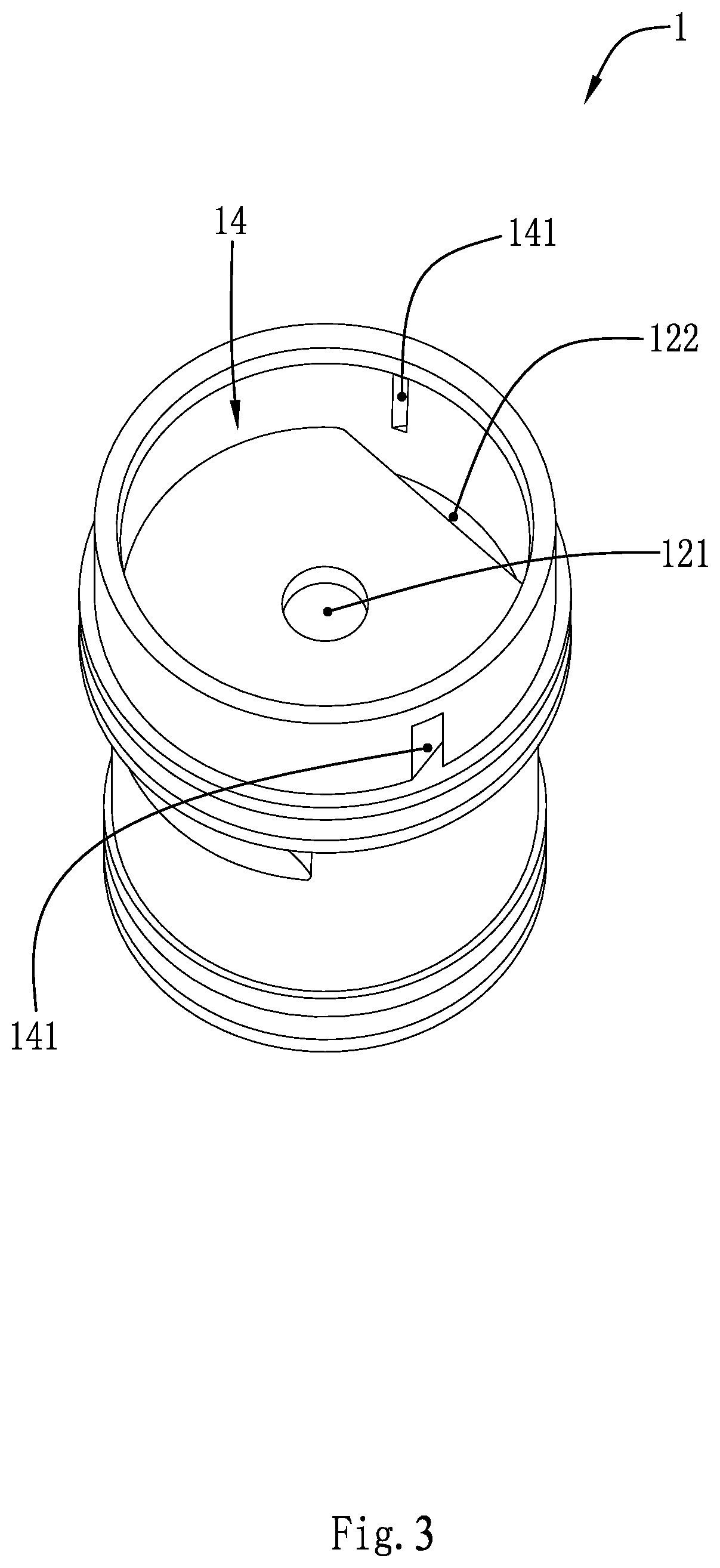
[0037]As shown in FIGS. 1 to 13, a light-emitting assembly with a micro hydraulic power generator includes a power generation module and a light-emitting module 4. The power generation module is formed by assembling a housing 1, a coil module 2 and an impeller 3. An accommodating space 11 inside the housing 1, as shown in FIGS. 4 and 5, is divided into two cavities by a transverse baffle 12 therein, which are a coil cavity 13 and an impeller cavity 14, respectively. The transverse baffle 12 is provided with a first perforation 121 at the center thereof, and a side wall of the impeller cavity 14 is provided with multiple water inlets 141. Each of the water inlets 141 is provided in the form of an obliquely cutout 1411 and is formed by obliquely cutting into the interior from an outer wall of the impeller cavity 14.

[0038]Two internally recessed portions 131 opposite to each other are provided at connection portions between an outer wall of the coil cavity 13 and the transverse baffle ...


PUM


Abstract

A light-emitting assembly with a micro hydraulic power generator includes a power generation module and a light-emitting module. The power generation module includes a housing, a coil module and an impeller. An accommodating space inside the housing is divided by a transverse baffle therein into two cavities, respectively a coil cavity and an impeller cavity. A side wall of the impeller cavity is provided with at least one water inlet. At least one internally recessed portion is provided at a connection portion between the transverse baffle and an outer wall of the coil cavity, and the transverse baffle defines a water outlet at a portion positionally corresponding to the internally recessed portion. The coil module is arranged in the coil cavity in a sealed manner by a colloidal material. The impeller is placed in the impeller cavity, the impeller can be rotated by an external force.

Description

CROSS REFERENCE TO RELATED APPLICATIONS[0001]This application is based upon and claims priority to Chinese Patent Application No. 202020502643.7, filed on Apr. 8, 2020, the entire contents of which are incorporated herein by reference.FIELD OF THE INVENTION[0002]The present disclosure belongs to the technical field of kitchen and bathroom appliances, and particularly relates to a light-emitting assembly with a micro hydraulic power generator.BACKGROUND OF THE INVENTION[0003]With the improvement of people's living quality, the use of technology in various fields is further refined. In the field of kitchen and bathroom appliances, for example, bath and shower accessories, kitchen and bathroom products that can output hot water have also been developed.[0004]However, in the process of practical use, it is necessary to activate certain lighting effects (lighting or visual effects) while water is being used in some scenes; or because it is not easy to control the temperature of the hot w...

Claims


Application Information

Patent Timeline
IPC IPC(8): F21S9/04F21V31/00F21V23/06F21V3/00F21V23/04H02K7/18F03B13/10F03B3/12
CPCF21S9/046F21V31/005F21V23/06F21V3/00F21Y2115/10H02K7/1823F03B13/10F03B3/12F21V23/0442Y02E10/20H02K7/14F21V31/04F03B13/00F05B2250/82F05B2210/403F05B2220/7066F05B2240/20F05B2240/57F05B2240/85F05B2220/706
Inventor LU, WENRONGYANG, WEI
Owner PPI XIAMEN IND
Why Eureka
Try Eureka