Method for shaping a fibrous preform by compacting in order to produce a composite material part

a technology of composite materials and fibrous preforms, which is applied in the field of tubular parts of tubular parts, can solve the problems of difficult evacuation of injection tools, altering the mechanical properties of composite materials, and difficult operation of fibrous texture shaping by compaction, etc., to achieve soften the fibrous structure, facilitate the shaping, and facilitate the effect of fibrous structur

Pending Publication Date: 2021-10-21
SAFRAN
View PDF6 Cites 0 Cited by
  • Summary
  • Abstract
  • Description
  • Claims
  • Application Information

AI Technical Summary

Benefits of technology

[0014]Such a heating softens the fibrous structure and facilitates its shaping without disturbing the weave(s) or weaving pattern(s) of the latter. Indeed, the sizing present on the yarns helps stiffen the fibrous structure, thus preventing the fibers of the weaving yarns from freely following the deformation imposed during compaction. By heating the fibrous structure to a temperature greater than or equal to the softening temperature of the sizing composition coating the yarns, the sizing momentarily loses its tackifying character, thus facilitating slippage between fibers. Moreover, with the shaping process of the present invention, it is no longer necessary to wet the fibrous structure for its compaction as is the case with the solutions of the prior art. The manufacturing time of a composite material part is thus shortened.
[0015]Furthermore, the pre-compaction step allows better control of the deformation of the fibrous structure and facilitates the closing of the forming tool during final compaction. Indeed, when the fibrous structure is wetted, the water acts as a lubricant that facilitates slippage between the yarns, thus reducing disruption or disturbance of the initial weave during compaction. When the structure is dry, i.e., free of water, there is no more lubricant between the yarns. The risk of disorganization of the woven yarns is therefore greater. To this end, the process of the invention proposes a pre-compaction step to reduce the thickness of the fibrous structure to an intermediate thickness that allows the application of a compaction force less than that necessary to reach the final thickness targeted for the preform, thus minimizing the impact of compaction on the organization of the structure yarns. Similarly, the final compaction is carried out with the structure in a pre-compacted state, i.e., already having a reduced thickness compared with its initial thickness. The compaction force for final compaction is also less than that required to reach the final thickness targeted for the preform without pre-compaction, thus minimizing the impact of compaction on the organization of the structure yarns. The pre-compaction step also facilitates the closing of the forming tool for final compaction because the structure already has a reduced thickness compared with its initial thickness at the exit of the loom.
[0016]Finally, the pre-compaction step being carried out in a different tool from that used for the final compaction step, it is possible to control the state of the structure between these two steps.
[0017]According to a particular feature of the process of the invention, the fibrous structure is free of water during the pre—compaction and final compaction steps. The absence of water in the fibrous structure during its shaping by compaction makes it easier to evacuate the tool during the injection of the liquid matrix precursor and to avoid the appearance of porosity in the composite material of the final part.

Problems solved by technology

The operation of shaping the fibrous texture by compaction is tricky because the weaving pattern or weave on the surface and at the core of the fibrous structure must not be altered.
However, once shaped, the preform must be dried in order to remove water, the presence of which is undesirable during the subsequent operations of injection and transformation of the liquid matrix precursor composition.
Indeed, water makes it difficult to evacuate the injection tool.
Moreover, during the transformation heat treatment of the liquid composition, water vapor can be trapped in the preform, leading to the formation of porosities in the final part which alter the mechanical properties of the composite material.
The risk of disorganization of the woven yarns is therefore greater.

Method used


Image

  • Method for shaping a fibrous preform by compacting in order to produce a composite material part
  • Method for shaping a fibrous preform by compacting in order to produce a composite material part
  • Method for shaping a fibrous preform by compacting in order to produce a composite material part

Examples


Embodiment Construction

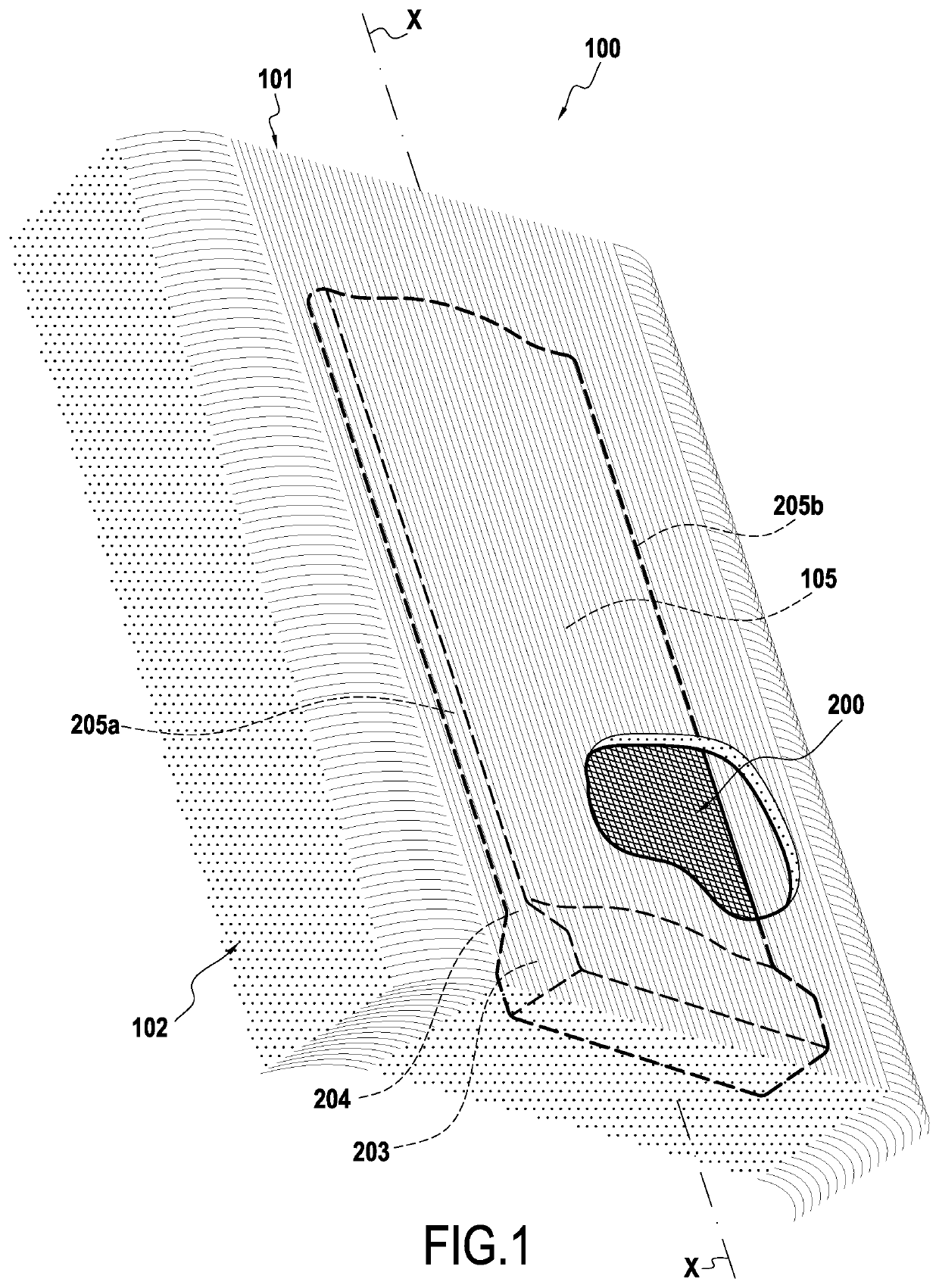
[0038]The invention generally applies to the production of composite material parts, the parts being produced from a fibrous preform into which a liquid precursor composition of a matrix material is injected and then transformed so as to obtain a part comprising a fibrous reinforcement densified by a matrix.

[0039]Hereinbelow, the present invention is described in application to the manufacture of a gas turbine composite material blade, such as an aeroengine blade.

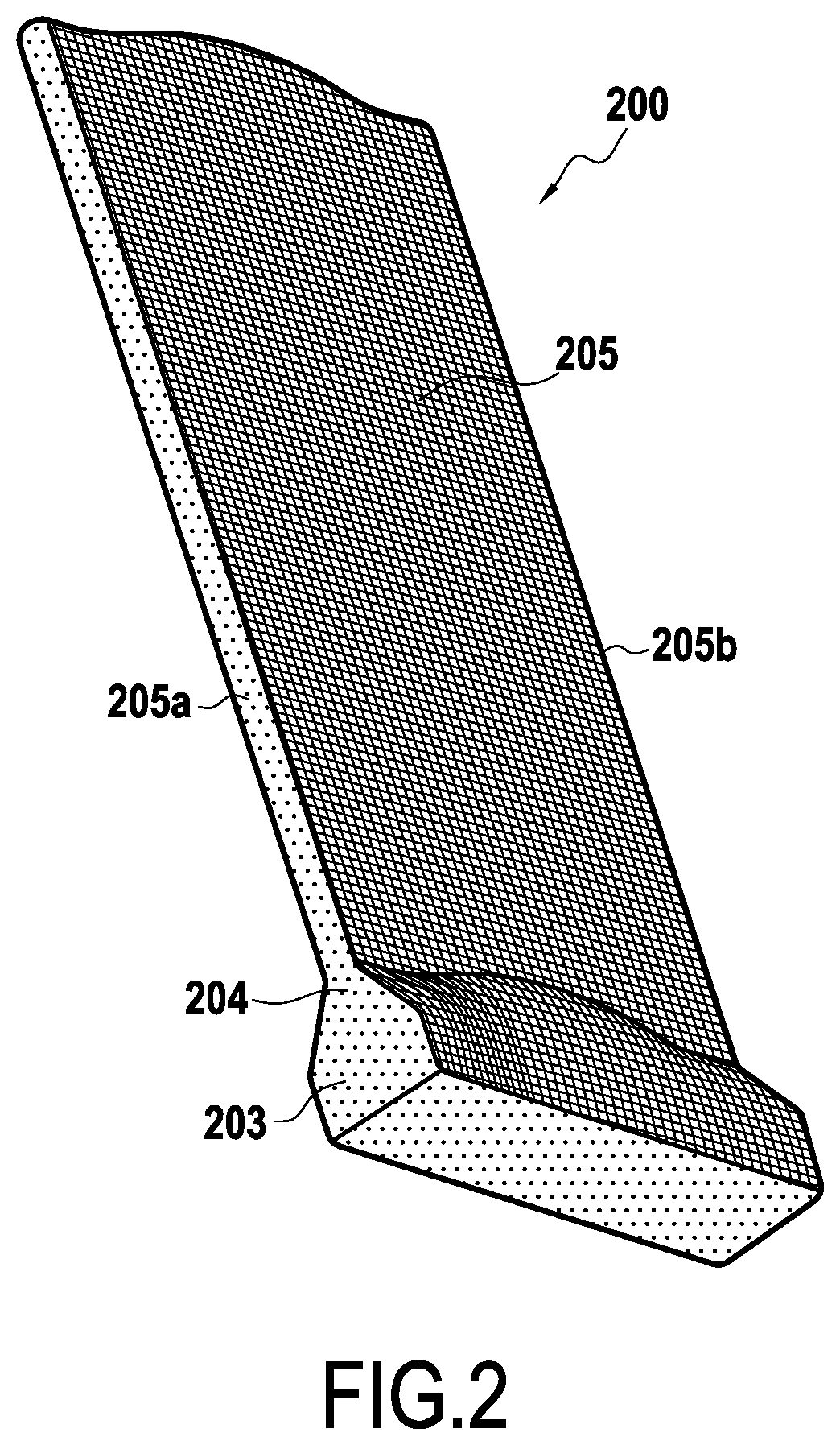
[0040]The process for manufacturing a composite material blade according to the invention begins with the production of a fiber blank obtained by three-dimensional weaving or by multilayer weaving.

[0041]As used herein, “three-dimensional weaving” or “3D weaving” means a weaving method in which at least some of the warp yarns bind weft yarns over several weft layers, for example an “interlock weave”. As used herein, “interlock weave” means a 3D weave in which each warp layer interlinks several weft layers with all the yarns ...


PUM

PropertyMeasurementUnit
softening temperatureaaaaaaaaaa
thicknessaaaaaaaaaa
temperatureaaaaaaaaaa

Abstract

A process for shaping, by compaction, a fibrous structure obtained by three-dimensional or multilayer weaving between a plurality of layers of warp yarns and a plurality of layers of weft yarns. The yarns of each plurality of layers of warp yarns and layers of weft yarns are coated with a sizing composition. The shaping includes a pre-compaction stage followed by a stage of final compaction of the fibrous structure. During pre-compaction and final compaction, the fibrous structure is at a temperature greater than or equal to the softening temperature of the sizing composition. The process further includes the cooling of the fibrous preform obtained after final compaction of the fibrous structure.

Description

BACKGROUND OF THE INVENTION[0001]The invention relates to turbomachine parts made of composite material comprising a fibrous reinforcement densified by a matrix, the matrix being obtained by injecting a liquid composition containing a precursor of the matrix into a fibrous preform.[0002]One target area is gas turbine blades for aeroengines or industrial turbines.[0003]The manufacture of a composite material blade comprises the following steps:[0004]a) production of a fibrous structure by three-dimensional or multilayer weaving,[0005]b) placement of the fibrous structure in a compacting and forming tool,[0006]c) shaping of the fibrous structure by application of a compaction pressure to the fibrous structure present in the compacting and forming tool so as to obtain a fibrous preform of the blade to be manufactured,[0007]d) placement of the fibrous preform in an injection tool,[0008]e) injection of a liquid precursor composition of a matrix material such as a resin into the fibrous p...

Claims


Application Information

Patent Timeline
Patent Type & Authority Applications(United States)
IPC IPC(8): B29C70/48B29B11/16B29C70/24B29C70/54F01D5/28
CPCB29C70/48B29B11/16B29L2031/082B29C70/543F01D5/282B29C70/24B29C70/548B29D99/0025B29L2031/08F05D2230/20
Inventor RAVEY, CHRISTOPHEFOUSSARD, OLIVIERLANFANT, NICOLAS PIERREPAYEN, DIDIERTOUZE, ADRIENVENAT, ROMAIN
Owner SAFRAN
Why Eureka
Try Eureka